PowerSeries - PC1616/PC1832/PC1864
4
1.5 AUX Power Wiring
The control panel can provide a maximum of 700mA of current for modules, powered detectors, relays, LEDs, etc. If the total current required
exceeds 700mA an additional power supply is required (e.g., PC5200, PC5204). See list below.
Min/max operating voltages for devices, sensors and modules is 9.5V
DC - 14VDC.
1.6 PGM Wiring
PGMs switch to ground when activated from the control panel. Connect the
positive side of the device to be activated to the AUX+ Terminal. Connect the
negative terminal to the PGM.
Current output is as follows:
• PGM 1, 3, 4 50mA
• PGM 2 300mA
For current levels greater than 300mA, a relay is required.
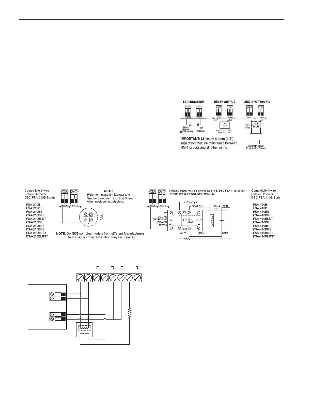
PGM2 can also be used for 2-wire smoke detectors.
NOTE: Use SEOL resistors on fire zones only.
LED output with current limiting resistor and optional relay
driver output
2-Wire Smoke Detectors Initiating Circuit
• Style B (Class B), Supervised, Power Limited
• UL Compatibility Identifier. . . . . . . . . . . . . . . . . . . . . . . . . . . . . . . PC18-1
• DC Output Voltage . . . . . . . . . . . . . . . . . . . . . . . . . . . . . . . .9.8-13.8 VDC
• Detector Load . . . . . . . . . . . . . . . . . . . . . . . . . . . . . . . . . . . . .2mA (MAX)
• Single End-of-Line (SEOL) Resistor. . . . . . . . . . . . . . . . . . . . . . . . .2200
• Loop Resistance. . . . . . . . . . . . . . . . . . . . . . . . . . . . . . . . . . . . 24(MAX)
• Standby Impedance . . . . . . . . . . . . . . . . . . . . . . . . . . . . . . . 1020
• Alarm Impedance. . . . . . . . . . . . . . . . . . . . . . . . . . . . . . . . . . 570(MAX)
• Alarm Current . . . . . . . . . . . . . . . . . . . . . . . . . . . . . . . . . . . .89mA (MAX)
UL Compatibility ID For FSA-210B Series is: FS200
NOTE: For ULC Listed installations use FSA-210A and FSA-410A series.
4-Wire Smoke Detectors
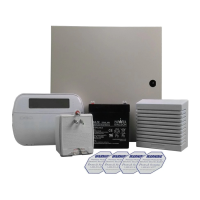
1.7 Carbon Monoxide Detector Wiring
RM-1/RM-2 POWER LOOP
SUPERVISORY RELAY
EOLR-2
END-OF-LINE
RESISTOR
5600 Ohm, 0.5W
2200 Ohm
END-OF-LINE
RESISTOR
EOLR-3
ALARM
INITIATING
LOOP
RESISTANCE
100 Ohm
12V
DC
CO DETECTOR
RM-1/RM-2
POWER LOOP
SUPERVISORY
RELAY
(12V
DC, 35mA)
ALARM
INITIATING
LOOP
RESISTANCE
100 ohm
SEOL
RESISTOR
(5600 ohm)
PC1616/1832/1864
ANY
COM
ZONE
INPUT
POWER ALARM TROUBLE
NC C NO NC C NO
ANY
Z
(SEOL TYPE 41)
AUX
+
+
-
-
+
-
DG009477
The following hardwired CO Detector models can be used
with PC1616/PC1832/PC1864 v4.5 (and higher) control
panels:
• Potter Model CO-12/24, UL File E321434
• Quantum Model 12-24SIR, UL File E186246
• NAPCO Model FW-CO12 or FW-CO1224, UL File E306780
• System Sensor Model CO1224, UL File E307195
NOTE: For multiple unit connections, the leads between CO detec-
tors need to be broken. The power supervision relay has to be pow-
ered from the last detector in the loop.
Wireless CO detectors are also available. When installing
wireless CO detectors, use only DSC model WS4913. A DSC
wireless receiver model RF5132-433 v5.1 (and higher) or DSC
keypad receiver models RFK55XX-433 (xx= 00/01/08/16/64)
v1.2 (and higher) are required when installing wireless CO
detectors. For more details on either the WS4913 CO detector
or the receivers, please refer to their respective installation
manuals.