Installation
12
4 INSTALLATION
4.1 TERMINAL DESCRIPTION
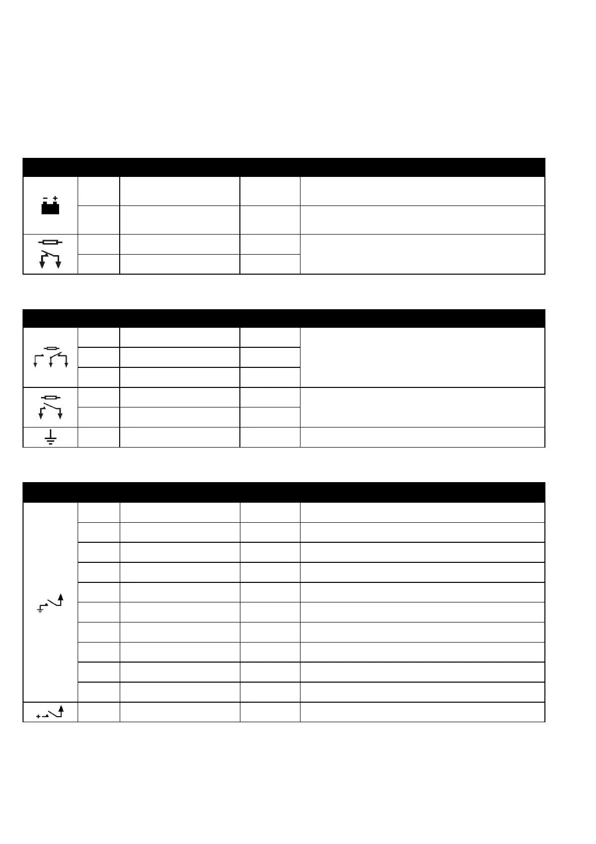
4.1.1 DC SUPPLY AND OUTPUT C
PIN No DESCRIPTION CABLE SIZE NOTES
1
DC Plant Supply Input
(Negative)
2.5mm²
AWG 13
2
DC Plant Supply Input
(Positive)
2.5 mm²
AWG 13
(Recommended Maximum Fuse 15A anti-surge)
Supplies the module (2A anti-surge requirement) and all output
relays
3 Output C
1.0mm²
AWG 18
Volts free relay normally configured to START/RUN generator
(2A rated)
4 Output C
1.0mm²
AWG 18
4.1.2 OUTPUTS D & E AND FUNCTIONAL EARTH
PIN No DESCRIPTION CABLE SIZE NOTES
5 Output D Normally Open
1.0mm²
AWG 18
Volts free relay change-over relay user configured (2A rated) 6 Output D Common
1.0mm²
AWG 18
7 Ouput D Normally Closed
1.0mm²
AWG 18
8 Output E
1.0mm²
AWG 18
Volts free relay user configured (2A rated)
9 Output E
1.0mm²
AWG 18
10 System Earth
1.0mm²
AWG 18
4.1.3 DIGITAL INPUTS
PIN No DESCRIPTION CABLE SIZE NOTES
11 Input A
1.0mm²
AWG 18
Configurable input. Connects to plant supply negative
12 Input B
1.0mm²
AWG 18
Configurable input. Connects to plant supply negative
13 Input C
1.0mm²
AWG 18
Configurable input. Connects to plant supply negative
14 Input D
1.0mm²
AWG 18
Configurable input. Connects to plant supply negative
15 Input E
1.0mm²
AWG 18
Configurable input. Connects to plant supply negative
16 Input F
1.0mm²
AWG 18
Configurable input. Connects to plant supply negative
17 Input G
1.0mm²
AWG 18
Configurable input. Connects to plant supply negative
18 Input H
1.0mm²
AWG 18
Configurable input. Connects to plant supply negative
19 Input I
1.0mm²
AWG 18
Configurable input. Connects to plant supply negative
20 Input J
1.0mm²
AWG 18
Configurable input. Connects to plant supply negative
21 Input K
1.0mm²
AWG 18
Generator ready input. Connects to plant supply Positive