Operation
28
6.4 LOAD SWITCHING CONTROL
The following timing diagrams detail the differences between the load switching control options.
6.4.1 BREAKER SCHEME A
NOTE : S2 Closed Auxiliary and S1
NOTE : S2 Closed Auxiliary and S1NOTE : S2 Closed Auxiliary and S1
NOTE : S2 Closed Auxiliary and S1Closed Auxiliary inputs d
Closed Auxiliary inputs dClosed Auxiliary inputs d
Closed Auxiliary inputs do not affect the operation of the
o not affect the operation of theo not affect the operation of the
o not affect the operation of the
load
load load
load
switching in
switching in switching in
switching in
Breaker Scheme A
Breaker Scheme ABreaker Scheme A
Breaker Scheme A
6.4.2 S1 / S2 LOAD INHIBIT
Activation of an input configured to S1 load inhibit or S2 load inhibit inputs cause the corresponding breaker to be
opened immediately. No other change in function will occur.
When the input is deactivated the breaker is closed again if appropriate.
6.4.3 LOAD SHEDDING
If an input configured to Load Shed is activated, outputs set to Open S1 and Open S2 will energise, and inputs
configured to Close S1 and Close S2 will de-energise. Open Mains Pulse and Open Gen Pulse outputs will only
energise if the corresponding supply was on load before application of the Load Shed input.
When the Load Shed input is deactivated, the load is transferred back to the supply that was disconnected
before application of the input.
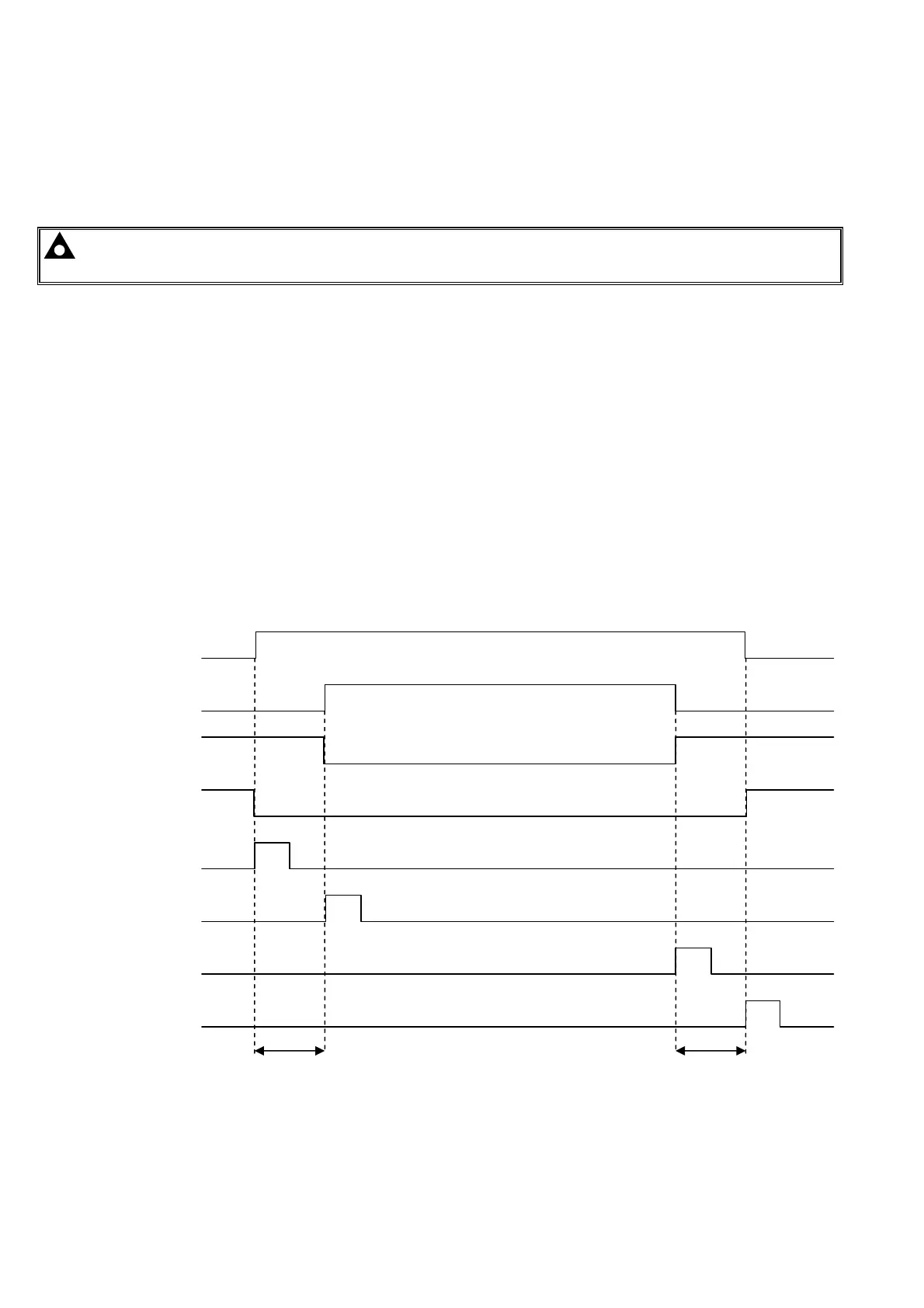
6.4.4 TIMING DIAGRAM
Open S1
Close S2
Close S1
Open S2
Open Mains Pulse
Close Gen Pulse
Close Mains Pulse
Open Gen Pulse
Transfer time Transfer Time