40
Dukane Manual Part No. 403–566–01
DPC
™
II Plus and EZ Welder System – User’s Manual
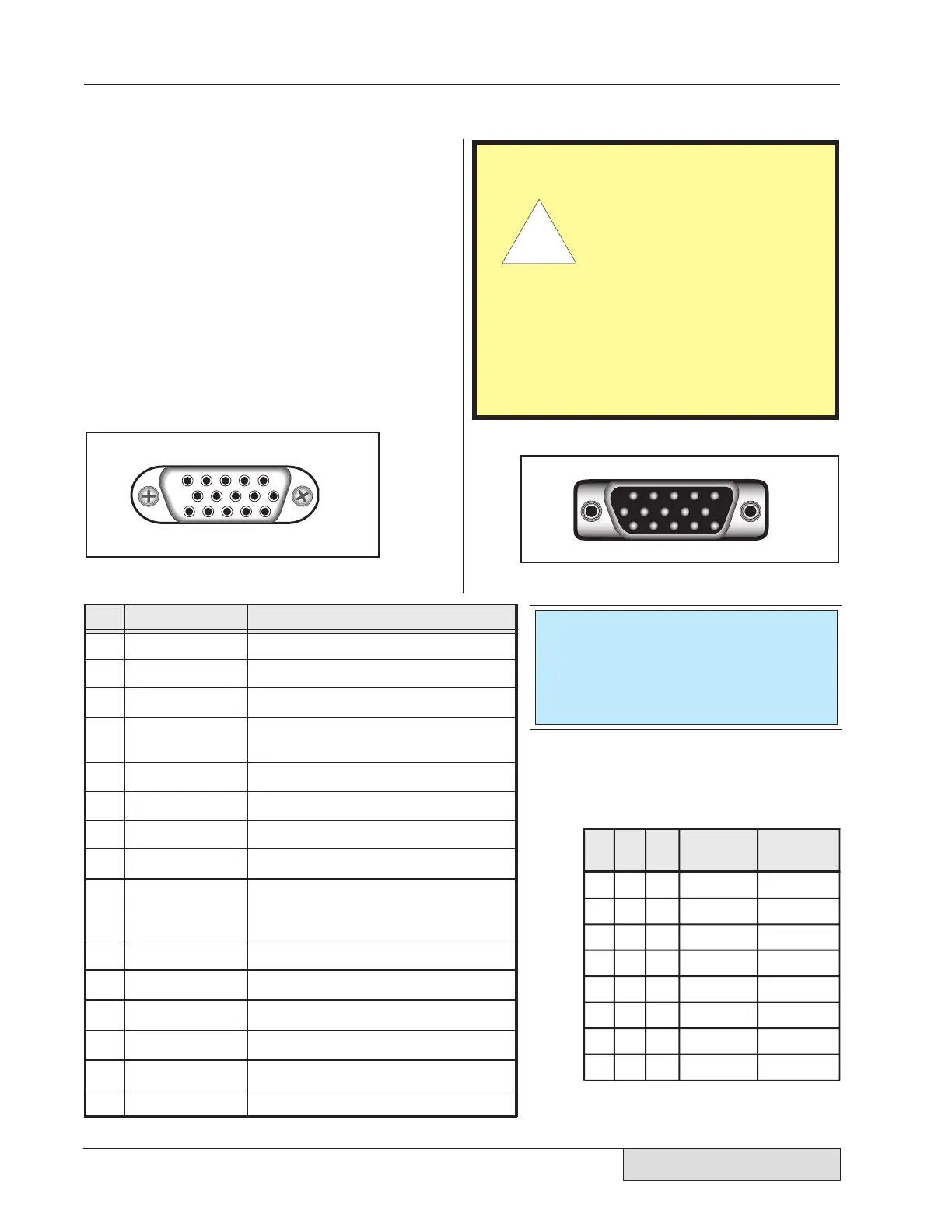
System Input Connector
The System Input is a HD-15 (high-density, 15
contact) female connector. Pin assignments are
shown in Figure 5–2. Table 5—I below lists the
pinout and signal name for the System Input con-
nector. A complete description of the input signals
and their function is given on the next page. Users
of custom automation will also find a list of wire
color codes for the Dukane 200–1203 I/O cable
assembly in Table 5—III. This cable is used to
connect the DPC to custom automation equipment
to control the welding process.
1 2 3 4 5
6
10
11 12 13 14 15
P
in
S
ignal Name
S
ignal Description
Iso Common Isolated Input Common (if jumper is
selected – Figure 5–9/SH707)
10
Not Used Reserved for Future Use
12
Setup I.D. Bit 0 Remote Setup Selection Bit #0 (LSB)
13
Setup I.D. Bit 1 Remote Setup Selection Bit #1
14
Setup I.D. Bit 2 Remote Setup Selection Bit #2 (MSB)
+22VDC Current limited to 250 mA maximum
1
Gnd 22VDC Return (DPC Chassis Ground)
2
Iso Oper In Isolated Operate Input
3
4
Iso Press Cntrl Isolated Press Control
5
Not Used Spare Input Pin
6
Gnd 22VDC Return (DPC Chassis Ground)
7
Sw Oper Input Switch Closure Operate Input
8
Iso Auto Stop Isolated Automation Stop Input
—OR—
Isolated Automation End–Of–Weld
(set by jumper SH704 see Figure 5–12)
9
15
F P Lock Front Panel Control Lock
11
Hand Probe Press InhibitHPPI
5 4 3 2 1
6
10
15 14 13 12 11
Pin
14
Pin
13
Pin
12
Timer
Setup File
MPC Probe
Selected
0 0 0 File 1
File 2
File 3
File 4
File 5
File 6
File 7
File 8
Probe 1
Probe 2
Probe 3
Probe 4
Probe 5
Probe 6
Probe 7
Probe 8
001
010
011
100
101
110
1
Note: 1 = Pin Grounded (to DPC chassis)
0 = Pin O
en (no connection)
11
Figure 5–3 Cable end of SYSTEM IN connector.
Table 5—
I System Input Connector Signals
Figure 5–2 HD-15F System Input Connector
Table 5—II Remote Setup File Selection
CAUTION
The System Input port
uses the same type of
connector as a standard
computer video monitor
port, but it is electrically
very different. DO NOT
connect any video monitor devices
to this connector. Doing so may re-
sult in damage to both the video
device and the DPC.
Ꮨ
NOTE
The connector pinout in Figure 5–2 is
the female DPC panel connector. The
male cable end is a mirror image and is
shown in Figure 5–3.