167
Dukane Manual Part No. 403–566–01
Appendix C – User Supplied Circuitry
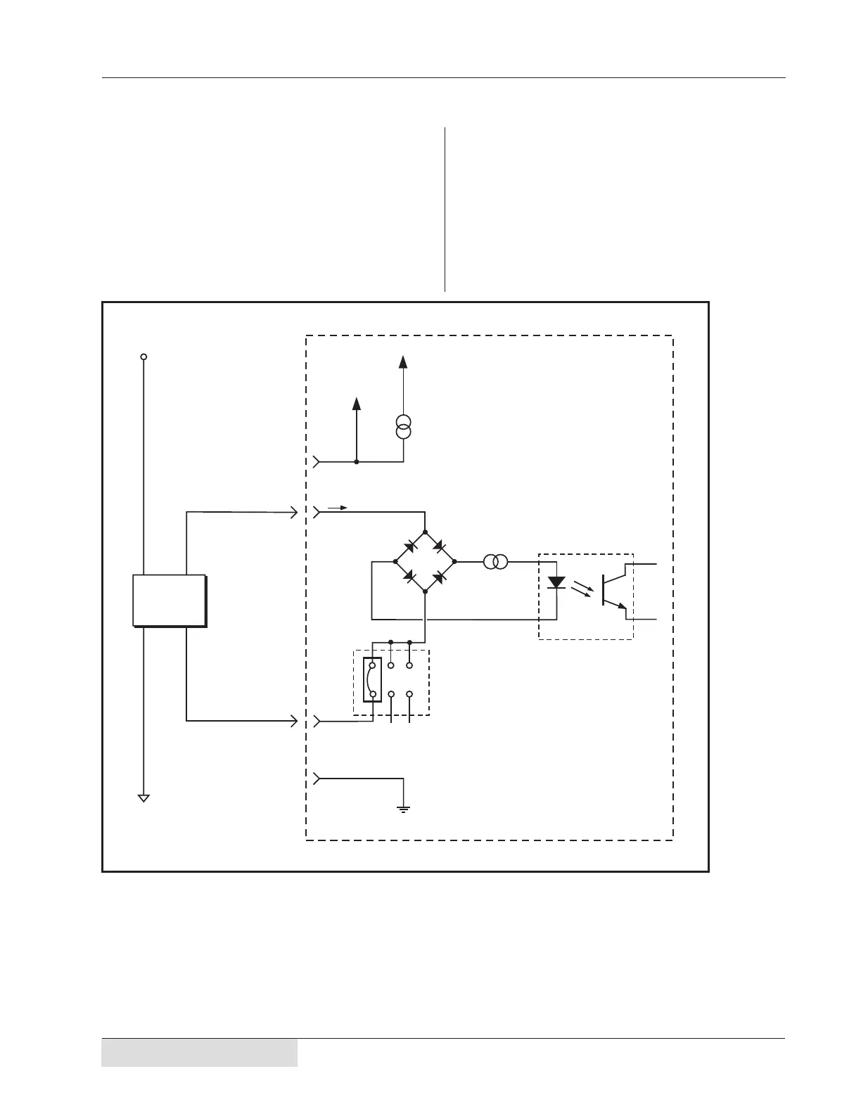
Isolated Switch Circuit
Isolated Current Source Circuit
Figure C–5 illustrates a fully isolated circuit con-
nected to the Isolated Automation Inputs. This re-
quires an external power supply to drive the switch.
The SH707 jumper block needs to be placed in
the JU726 position (refer to Figure 5–12).
DPC Ground
+22V
DPC Internal
Power Supply
Current
Limit Circuit
250mA max.
Pin #2 & Pin #7
Isolated Input
High–Side
Isolated Input
Low–Side
Automation
Ground
+5 to +24V
Automation
Power Source
Isolated
Current
Source
Pin #3 – Operate
Pin #5 – Press Control
Pin #9 – Auto Stop
Pin #4 – Iso Common
No Connection
Pin #1
No Connection
Jumper Block SH707
Position JU726
(Refer to Figure 5–12)
+24V
Internal
DPC II Plus
Circuitry
Optical Isolation
Circuit
User
Supplied
Switch
Circuitry
Current
Limit Circuit
12.5 mA
max.
12.5 mA
max
4 mA
min
Figure C–5 Isolated Current Source


 To Next Page