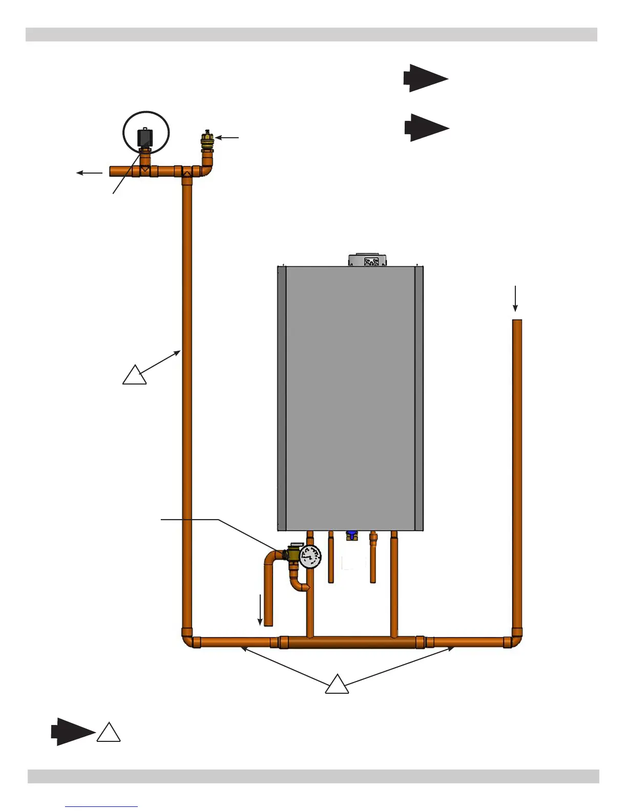
37
Piping Diagram - LWCO Location
LOW WATER CUTOFF
Low Water Cutoff (LWCO)
(See Figure 3 for detail)
Air Vent
Supply
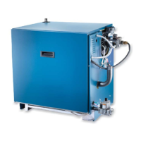
Gas
Boiler
Safety Relief
Valve
Position LWCO Above
Top of Boiler
1
DO NOT PLACE ISOLATION VALVE
BEFORE TEE OR LWCO.
Note
1
*To Drain
* Check Local Codes for
Maximum Distance to
Floor.
Arrange piping to prevent water
dripping onto boiler.
1
Return
Note
Illustrations are meant to show
system piping concept only. Installer
is responsible for all equipment and
detailing required by authority having
jurisdiction.
Note
PN 240011430 REV G, [03/31/18]