5
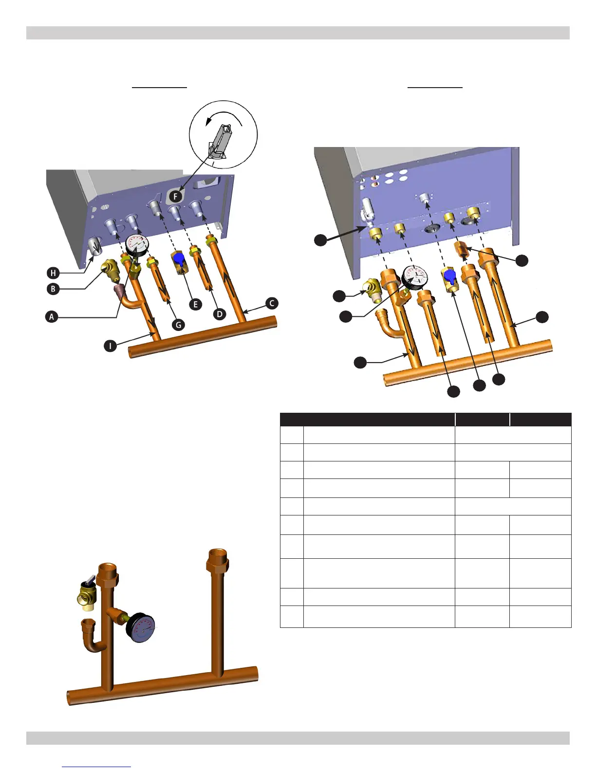
LABOR SAVING PIPING MANIFOLDS / NEAR BOILER PIPING CONNECTIONS
150 COMBI
205 COMBI
LEGEND 150 205
A Pressure Gauge -
B Pressure Relief Valve 30.00 psi [2.11 bar]
C Heating return connection 3/4" [22.2mm] 1” [25.4mm]
D
Cold DHW inlet tap / system lling
connection for Combi
1/2"
[15.9mm]
3/4"
[22.2mm]
E Gas shutoff connection 3/4" [22.2mm]
F Boiler lling connection (some models)
1/2"
[15.9mm]
na
G
DHW outlet/indirect storage tank
connection
1/2"
[15.9mm]
3/4"
[22.2mm]
H Drain connection for condensate
13/16” [21mm]
ID
Hose
3/4 NPT
I Heating supply connection 3/4" [22.2mm] 1” [25.4mm]
K
5 gpm D H W o w r estricto r
(Factory installed) (205 only)
na
3/4"
[22.2mm]
A
B
H
I
G
E
D
C
K
MANIFOLD
150/205
PN 240011430 REV G, [03/31/18]