T5L_ASIC Development Guide
D
WI
N
T
echnology
Pro
f
essional
,
Credi
t
able
,
Success
f
ul
3.4 Timer
T5L OS 8051 has three timers: T0/T1/T2, of which T0/T1 are consistent with standard 8051, and
T2 can only work in 16 bit autoload mode.
The clocks of T0 and T1 are 1/12 of the CPU main frequency. The clocks of T2 can be configured
as 1/12 or 1/24 of the CPU main frequency.
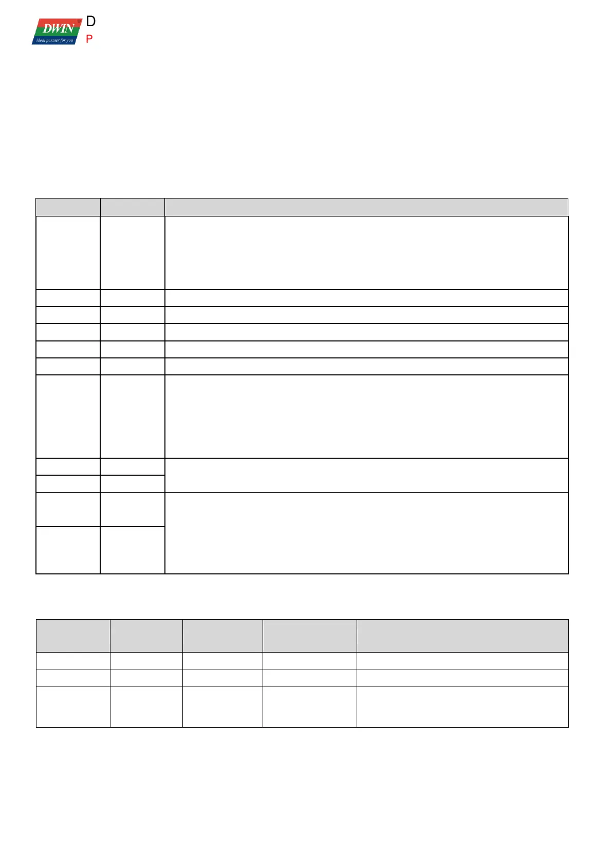
The relevant SFRs are shown in the table below
T0, T1 control registers, same as standard 8051, can be addressable by bit
.7=TF1 .6=TR1 .5=TF0 .4=TR0 .3=IE1 .1=IEO .0=ITO
IT1 and IT0 are external interrupt trigger mode selection:
0 = low level trigger 1 = down-jump edge trigger.
T0, T1 mode selection, same as standard 8051.
The T2 control register can be addressable by bit.
.7:clock frequency division selection. 0=CPU main frequency /12; 1=CPU main frequency/24;
.6-.4:must write 1;
.3-.1:must write 0;
.0:TR2. 1=T2 run; 0=T2 close;
T2 running value, automatically loaded every time counting overflow
TH2=CRCH TL2=CRCL.
The reload value of T2 = 65536-T2 timer interval (uS)*T2 clock frequency (MHz).
CPU main frequency = crystal frequency * 56/3, corresponding CPU main frequency/12 =
crystal frequency * 14/9, CPU main frequency/24 = crystal frequency * 7/9.
For example, the CPU main frequency is 206.438 MHz, T2 chooses 1/12 frequency division,
and the setting value of 1 mS timer interval is 48333 (0xBCCD).
The relevant settings of timer interrupt are as follows:
Interrupt enabling
control
Automatic clear TF0 in interrupt response
Automatic clear TF0 in interrupt response
After interrupt response, TF2 needs to be
cleared by software, otherwise interrupt will be
triggered again.
 Loading...