T5L_ASIC Development Guide
D
WI
N
T
echnology
Pro
f
essional
,
Credi
t
able
,
Success
f
ul
4 Simulation Debug
With the help of HME05 simulator (need to install the corresponding USB driver), users can connect
T5L JMARK interface and debug code IAP and run simulation under Keil development environment.
Note
(1) JMARK interface must be selected to OS CPU, and must be JMARK mode, that is, OS/GUI
(PIN#32) = 0 JMARKS (PIN#34) = 1 .And when the 4.3 inch evaluation board is used for simulation,
the jumper pad on the JMARK interface side is disconnected.
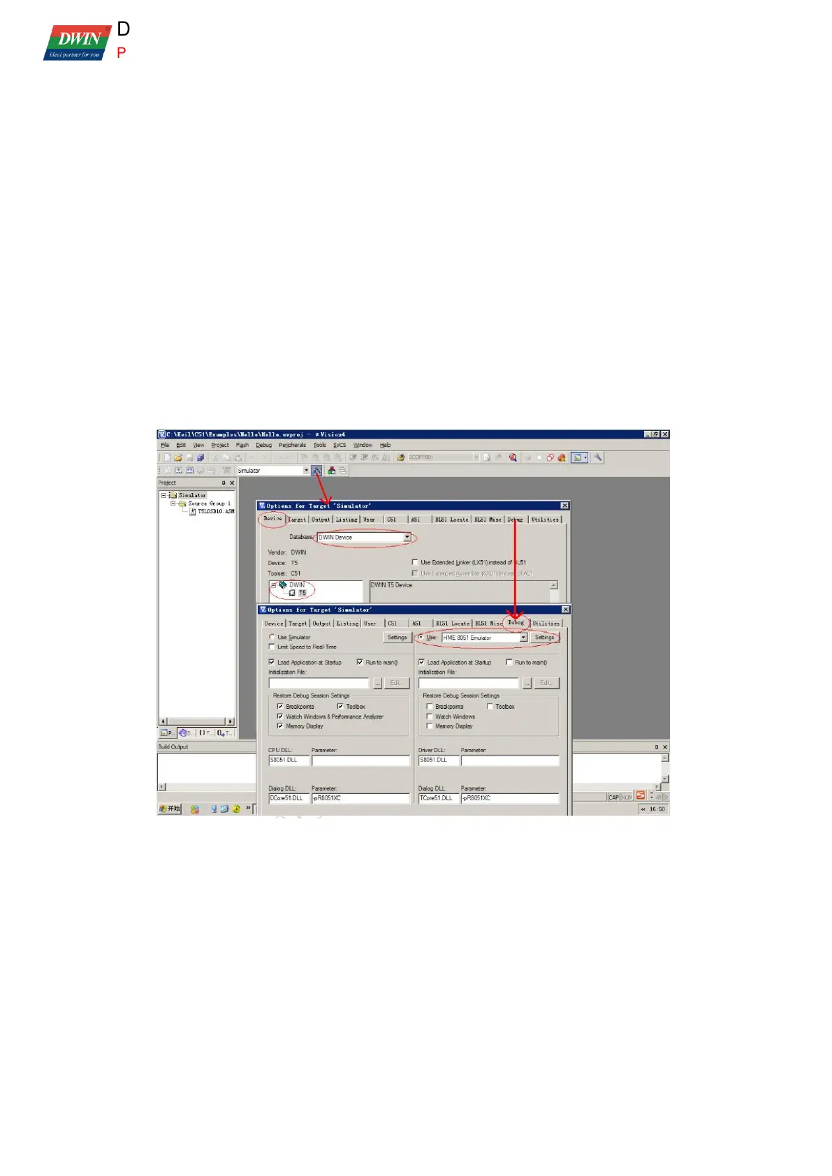
(2) The AGDI driver is installed to enable Keil to support T5 and HME05 simulators. After installation,
select and configure according to the following figure. After installation, copy the header file of T5L
OS CPU (*. INC or *. h) to KEIL/C51/INC/DWIN directory.
(3) Before setting the breakpoint to read the content of data storage (XDATA), DPC = 0x00 must be
ensured, otherwise the data will be misaligned.
(4) Before simulation, it is necessary to ensure that the OS CPU code address 0x00F8 of T5L
Flash starts with 0xFF FF 44 57 49 4E 54 35, otherwise the JMARK interface of OS CPU is
prohibited and HME05 emulator cannot be connected.
 Loading...