T5L_ASIC Development Guide
D
WI
N
T
echnology
Pro
f
essional
,
Credi
t
able
,
Success
f
ul
3.7 UART
3.7.1 UART2
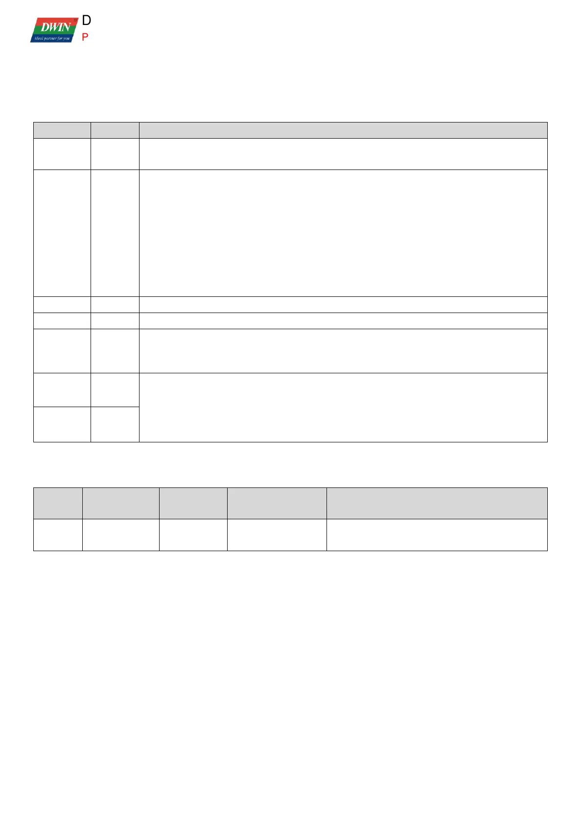
UART2 related SFR are shown in the following table.
.6 1 = UART2 interface leads to P 0.4 and P 0.5;
0 = UART02 interface does not lead out, it works as an IO port .
UART2 control interface, the same as standard 8051, can be addressable by bit.
.7=SM0
.6=SM1
.5=SM2(multiprocessor communication bit)
.4=REN0
.3=TB80
.2=RB80
.1=TI0
.0=RI0.
UART2 transceiver data interface
Baud rate generator selection, 0x00 = T1 timer (standard 8051), 0x80 = SRELOH: L.
.7 SMOD baud rate frequency doubling selection.
0 = no frequency doubling
1 = frequency doubling.
When ADCON = 0x80, SRELOH:L is used to set the baud rate without occupying T1.
SMOD=0 SREOH:L=1024-CPU main frequency/(64*baud rate)
SMOD=1 SREOH:L=1024-CPU main frequency/(32*baud rate)
CPU main frequency = crystal frequency * 56/3, 11.0592 MHz crystal corresponds to 206.4384 MHz
main frequency.
The relevant settings for UART2 interruption are as follows:
Interrupt enabling
control
RIO(SCON0.0)
TIO(SCON0.1)
After interruption, software needs to clear the
interruption trigger mark.
 Loading...