T5L_ASIC Development Guide
D
WI
N
T
echnology
Pro
f
essional
,
Credi
t
able
,
Success
f
ul
3.7.2 UART3
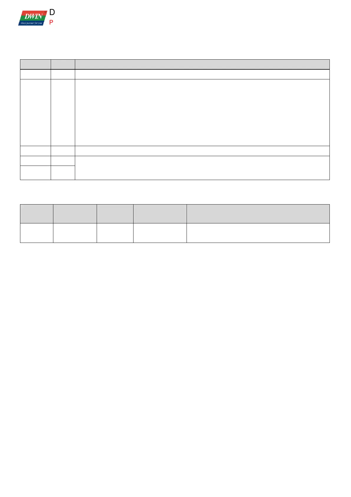
UART3 related SFRs are shown in the following table.
.5 1 = UART3 interface leads to P 0.6, P 0.7, 0 = UART3 interface does not lead out, it is IO port.
UART3 control interface, it is not addressable by bit.
.7 0=9bit UART; 1=8bit UART;
.6 Undefined;
.5=SM2(multiprocessor communication bit )
.4=REN .3=TB8 .2=RB8 .1=TI .0=RI.
Clearing the SCON1 bit mark requires two consecutive writings, such as
ANL SCON1,#0FEH
ANL SCON1,#0FEH
UART3 transceiver data interface
UART3 baud rate setting (CPU main frequency = crystal frequency * 56/3, 11.0592 crystal corresponding
to 206.4384 MHz main frequency):
SRE1H:L=1024-CPU main frequency/(32*baud rate)
The relevant settings for UART3 interruption are as follows:
Interrupt enabling
control
After interruption, software needs to clear the interruption
trigger mark.
 Loading...