T5L_ASIC Development Guide
D
WI
N
T
echnology
Pro
f
essional
,
Credi
t
able
,
Success
f
ul
3.7.4 UART5
The relevant settings of UART5 are as follows:
UART5 sending control:
.7 UART5 sending enables. 0=close;1=open;
.6 0=8bit mode,1=9bit mode;
.5 TB8, 9
th
bit sent in 9bit mode;
.4-.1 Write 0;
.0 TI, send flag. The position at which the stop bit is sent.
UART5 receive control:
.7 UART5 sending enables. 0=close;1=open;
.6 Write 0;
.5 TB8, 9
th
bit received in 9bit mode;
.4-.1 Write 0;
.0 R RI, receive mark. Set when the stop bit is received when a valid stop bit is received.
UART5 sending data interface
UART5 receiving data interface
UART5 baud rate setting
BODE3_DIV_H:L=CPU main frequency/(8*baud rate)
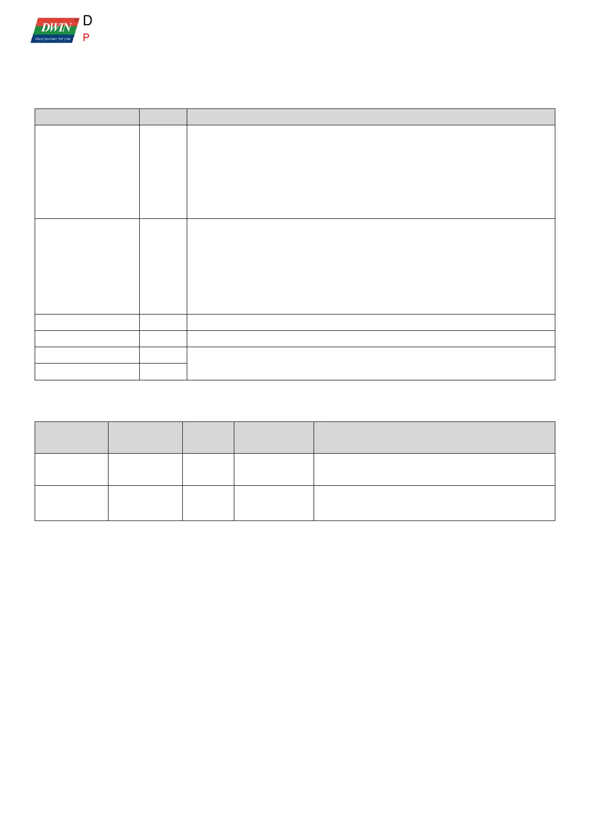
The relevant settings of UART5 interruption are as follows:
Interrupt enabling
control
After interruption, clear the interruption trigger mark by
software.
After interruption, clear the interruption trigger mark by
software.
 Loading...