No. 60027, Issue 4. January 1998
5 Installation 23
2A
2A
21W
10W
21W
10W
2A
2A
2A
2A
10W
6W
10W
6W
Rear
Front
Right
Indicator
Left
Indicator
Right
Side
Lights
Left
Side
Lights
13.5V
Right
Left
Side
SLM
Connector
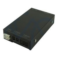
SLM-TÜV Lighting Connections
The three lighting outputs are: Pin 2 Side Lights
Pin 3 Left Indicators
Pin 4 Right Indicators
Note : The SLM-TÜV is designed to blow fuses leading to shorted lamps. When
wired as shown, a blown fuse will not prevent other lamps on the same circuit from
continuing to operate.
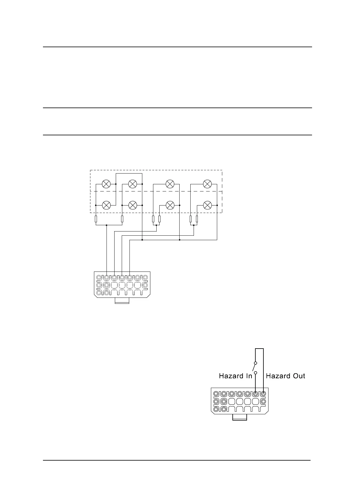
Hazard Switch
An external Hazard Switch can be
connected between Pins 6 and 7. When
this switch is closed, both indicator
outputs will flash synchronously at a rate
of 75 flashes per minute.