No. 60027, Issue 4. January 1998
7 Programming38
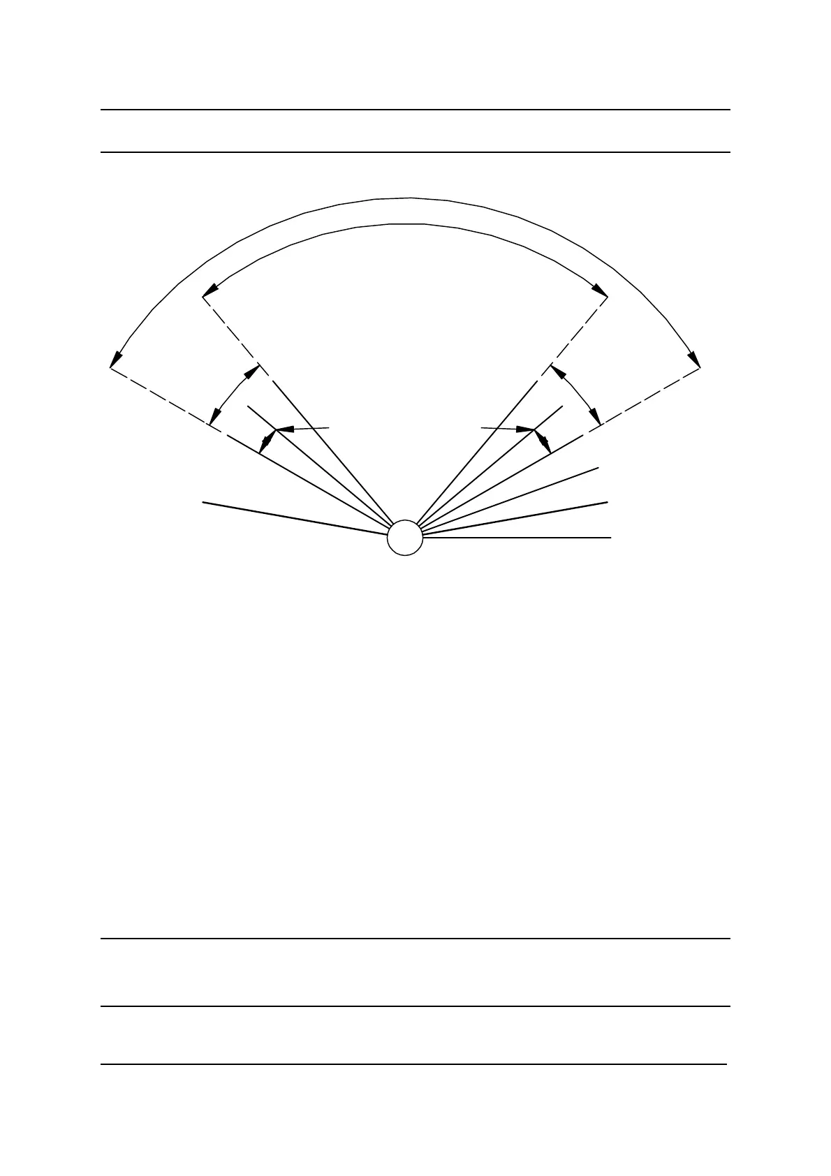
Position
Sense
Pot
0 V
1
0
0
%
0
%
SP+
Max Pot End V
Min Pot End V
Right Lock
Left Lock
Pot Voltage Tolerance
Lock Margin
Lock Margin
Actual Lock Limits
Physical Pot Limits
Parameter Purpose
Left Lock The ratio of the Position Sense Pot Wiper voltage to
the full pot voltage when the steering wheels are
Range 5 - 95 % moved as far left as is mechanically possible.
Accessed by : Dealer / User
HHP calibrated A physical limitation calibrated using the HHP - refer
to section 7.5.
Right Lock The ratio of the Position Sense Pot Wiper voltage to
the full pot voltage when the steering wheels are
Range 5 - 95 % moved as far right as is mechanically possible.
Accessed by : Dealer / User
HHP calibrated A physical limitation calibrated using the HHP - refer
to section 7.5.
Note: The Left and Right Lock parameters must not both be above nor both be
below 50%. Typically one will be around 25% and the other around 75%, so that
the total will be around 100%.