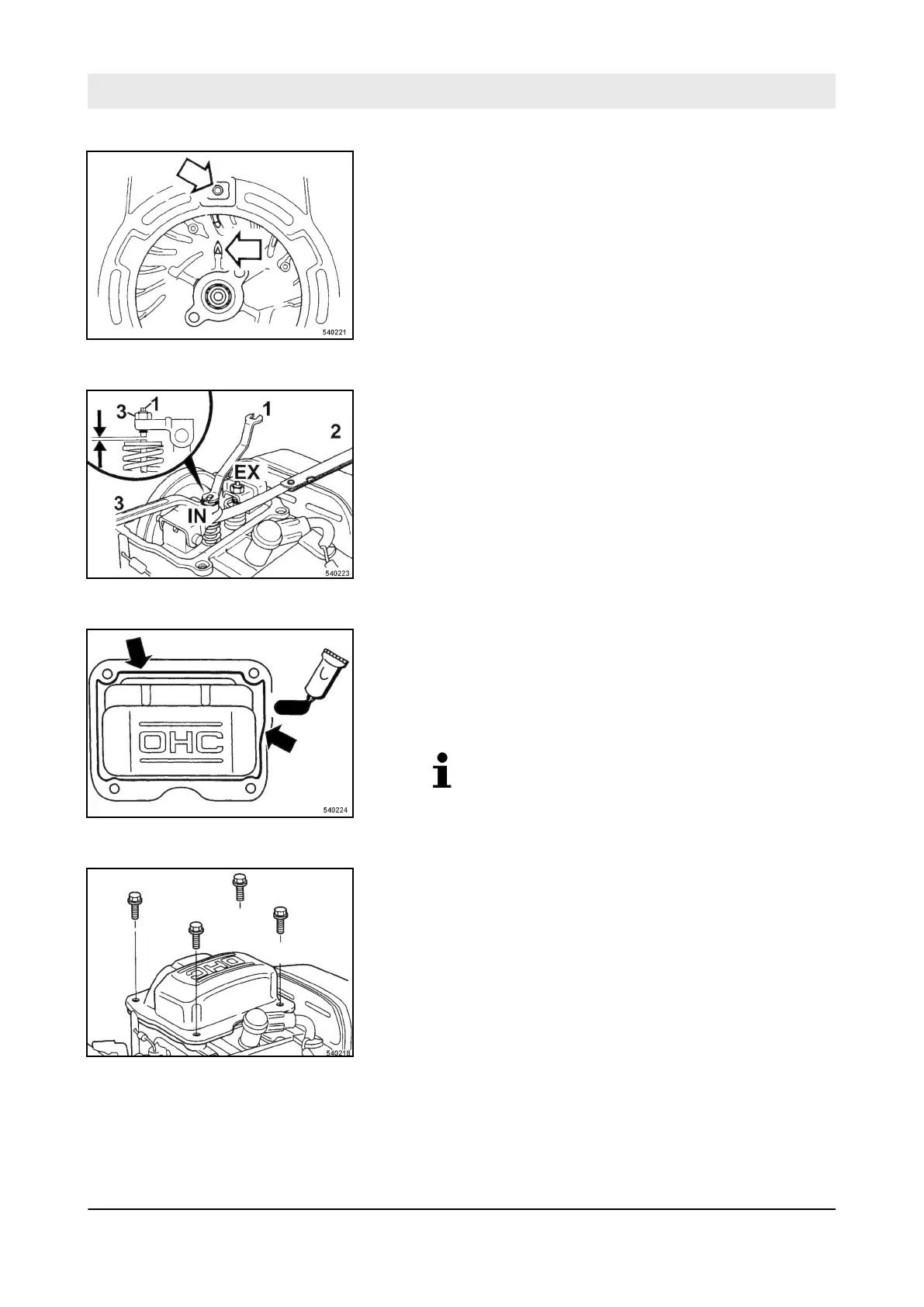
5. Align the alignment mark on the flywheel rib with the top bore
of the fan cover.
ð
The piston is in top dead centre position of the compres-
sion stroke.
6. However, if the exhaust valve is open when aligning the
marks, the flywheel must be turned further by 360°.
7. Check the valve clearance with a feeler gauge (2).
8. T
o adjust the valve, hold the valve adjustment screw (1) and
loosen the locking nut (3).
9. T
urn the valve adjustment screw in or out, as required.
10. Retighten the locking nut, tightening torque:
8 Nm (6 ft·lbf).
11. Clean the sealing faces on cylinder head cover and cylinder
block.
12. Apply a bead of liquid sealant, approx.
1.5 to 2.0 mm
(0.06 to 0.08 in) in diameter, to the inner side of the cylinder
head cover.
Liquid sealant: Three Bond 1207B or similar.
13. Attach the cylinder head cover to the cylinder block within the
next 10 minutes.
14. T
ighten the fastening screws.
Fig. 68
Fig. 69
Fig. 70
Fig. 71
Maintenance – Annually
DR6X
79