DYNATRON SOLARIS® PLUS DESCRIPTIONS AND DIAGRAMS
DYNATRON SOLARIS
®
PLUS SERIES | SERVICE MANUAL REV. 6 | AUGUST 29, 2017 116
Dynatron Solaris
®
Plus
Descriptions and Diagrams
Dynatron
®
Solaris
™
Plus Description
• e Main Board provides routing for communications and power to all boards in the system
• e CPU uses an Analog Devices Blackn processor and Flash memory to control the resources located on the
various treatment boards and to communication with the User Interface board
• e Light Mezzanine controls the Light Pad and Light Probe
• e STIM 1-2 board connects directly to the Main board and has pass through connections from the Main for the
Ultrasound board and the STIM 3-4 board
• e STIM 1-2 board communicates
and provides output signals to the
STIM 3-4 board
• e SD card interface allows for
eld updates of the Operating
soware to the CPU
• e Display / Keyboard provides
for the User Interface (cap sense
switches) and drives the liquid
crystal display for user feedback
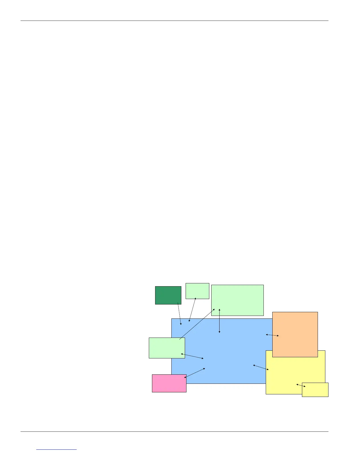
Dynatron
®
Solaris
™
Plus Block Diagram
Main Board
CPU
Light
Mezzanine
STIM 1 – 2
Board
Keypad / Display
Board
SD Card
Interface
Power
Supply
STIM
3 – 4
Ultrasound
Board
Block Diagram