HIGH VOLT INSTRUCTIONS
DYNATRON SOLARIS
®
PLUS SERIES | SERVICE MANUAL REV. 6 | AUGUST 29, 2017 43
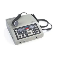
be sure the dispersive electrode is at least twice the size (in area) of the combined sizes of the active electrodes. e bifurcated
lead wire extension is an optional accessory available through Dynatronics.
During the treatment current ows in one direction
between the active and dispersive electrodes.
Changing the polarity in the treatment parameters
has the eect of reversing the direction of the current
ow between electrodes. It is important to attach the
active electrode to the HV Active (+) output of the
lead wire to ensure you are delivering the selected
polarity. e Lead wires are labeled: HV Active (+),
HV Dispersive (-) delivery.
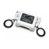
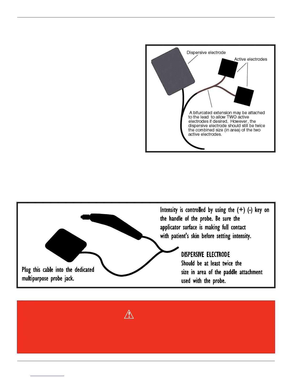
High Volt Probe Treatment Setup
is attended form of High Volt therapy is delivered
using the Dynatronics’ optional MultiStim probe in
conjunction with a dispersive electrode. is
hand-held probe is connected to the STIM PROBE
OUTPUT JACK located on the right-side of the
Solaris Plus device. e MultiStim probe intensity is
controlled on the probe itself.
High Volt electrodes with bifurcated active lead.
WARNING
When setting intensity, the probe must be in contact with the patient’s skin. Be sure that the patient can feel the
current as you increase the intensity. Do not increase intensity for probe treatments if the patient is unable to report
feeling the current.