SOUNDHEAD OPTIMIZATION ADDING OR REPLACING SOUNDHEADS
DYNATRON SOLARIS
®
PLUS SERIES | SERVICE MANUAL REV. 6 | AUGUST 29, 2017 84
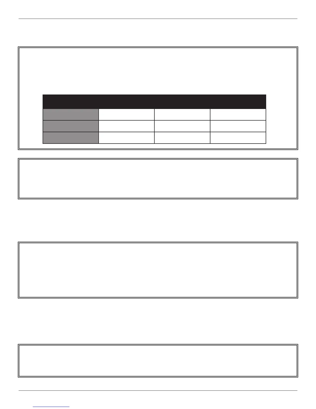
Dynatronics Soundhead Sample Parameters Printout
2. Turn the Solaris Plus Device OFF. Plug in the new soundhead. Turn the Solaris Plus ON.
3. Press the SOUND key followed by the FUNCTION KEY.
4. As a default, FREQUENCY should appear in the PARAMETER window and 1 MHz in the FREQUENCY window.
Using the Up/Down arrow keys located next to the FREQUENCY display, select the FREQUENCY value for 1 MHz
listed on the Parameter’s printout.
NOTE: THE NUMBERS ABOVE ARE PROVIDED FOR ILLUSTRATION ONLY AND SHOULD NOT BE
ENTERED INTO YOUR DYNATRON DEVICE. USE ONLY THE ACTUAL NUMBERS PROVIDED WITH
YOUR OWN SOUNDHEAD.
Serial: Manufacture Date: 9/15/2012
Size (cm): 5
Cal Date: 9/15/2012
Unit #: Solaris Plus
IHT:
1 MHz 2 MHz 3 MHz
Frequency
1750 1950 2050
Impedance
461 1064 699
Temperature
8 8 8
Example / Do NOT USE
NOTE: e Solaris Plus device will automatically recognize the size of the soundhead plugged into the console. To
verify that you are entering the parameters for the correct soundhead, make sure that the HEAD SIZE that appears
on the le-hand side of the Treatment Display Screen is correct. For example, if “5” is displayed, it means the device
senses a 5 cm
2
soundhead is plugged into the console. If correct soundhead size is not visible, use the arrow keys
next to the HEAD SIZE display to select the correct soundhead size.
NOTE: Parameters must be entered for all three FREQUENCY options 1 MHz, 2 MHz, and 3 MHz shown on the
Parameters printout for Frequency, Impedance, and Temperature.