CV3100 series and MINI series high performance general purpose inverter instruction manual
3-3
(3)Only the qualified professional who has been trained and authorized can
perform the wiring operation.
(4) Please pay attention that before energizing, check whether the voltage class
of inverter is identical with the supply voltage, otherwise, it would result in
person casualty and damage of device.
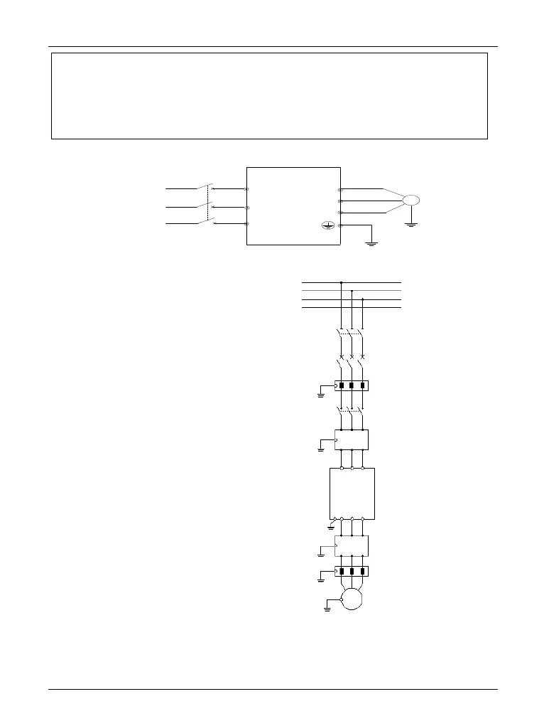
3.4 Wiring of main circuit terminal
M
R
S
T
U
V
W
CV3100
Power
Circuit
breaker
Diagram 3-3 Simple wiring of main circuit
3.4.1 Connection of inverter and option
(1) Between power grid and inverter,
breaking equipment like isolating
switch shall be installed for human
safety and compulsive power cutting
during maintaining the device.
(2) The supply circuit of inverter must be
mounted with the fuse or circuit
breaker with over current protection, to
avoid the spread of fault.
(3) When the power supply quality of
power grid is not quite high, an AC
input reactor shall be mounted
additionally. The AC reactor also can
improve the power factor of input side.
(4) The contactor is only for control of
power supply.
Diagram 3-4 Connection of inverter and option
Input EMI filter (optional)
AC input reactor (optional)
AC output reactor (optional)
Output EMI filter (optional)
 Loading...