CV3100 series and MINI series high performance general purpose inverter instruction manual
3-12
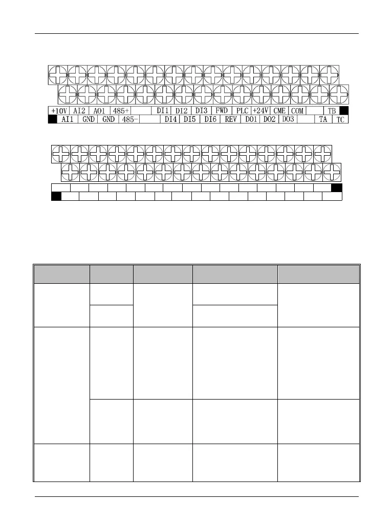
3.6 Control circuit configuration and wiring
3.6.1 Layout of control circuit terminal CN3 as follows(CV3100 series):
Diagram 3-9 Diagram of control panel terminals arrangement(0.7KW-7.5KW)
Diagram 3-10 Diagram of control panel terminals arrangement(11KW and
above)
3.6.2 CN3 Description of J1 terminal function shown as table 3-4
RS485
communication
interface
RS485 differential signal
positive terminal
Standard RS485
communication interface
and twisted pair line or
shielded line
RS485 differential signal
negative terminal
Multi-function
output terminal
Open collector
output terminal
Programmable
multi-function digital output
terminal is referred to the
introduction about output
terminal function of
terminal function parameter
P4.07、P4.08.
(Common terminal: COM)
Optic-coupling isolation
output
Working voltage:9~30V
Max output
current:50mA
Refer to P078 parameter
description for using
methods.
High speed
Opto-Couplers
output
Output 0-20KHz pulse
single, corresponding to
output frequency, current,
motor rev, voltage etc.
Opto-Couplers isolated
output, working voltage
range: 24V, max output
current: 50mA
Normal:TA-TB NC;
TA-TC NO
Fault:TA-TB NO;
TA-TC NC (refer to P4.09)
Rating of contact
NO:5A 250VAC
NC:3A 250VAC
+10V
AI1
AI2
AO1
GND GND
485+
485-
DI1
DI4
DI2
DI6
DI3
FWD
COM
COMDI5
DO1 DO2 +24V PLC TB
REV DO3 TA
TC