CV3100 series and MINI series high performance general purpose inverter instruction manual
3-11
breaker
forward
reverse
Multi-function terminal 1
0-10V analog
Signals input
0-20mA analog
Signals input
L
N
Breaking resistor
P+
PB
FWD
REV
DI1
DI2
DI3
DI4
DI5
DI6
U
V
W
M
10V
AI2
GND
AI1
485-
485+
GND
+12V
TC
TB
TA
DO1
AO1
GND
0-10V analog signals output
Multi-function Digital output(oc)
Programmable relay output
12V power supply
RS485 communicaiton
MINI-S
GND
Multi-function terminal 2
Multi-function terminal 3
Multi-function terminal 4
Multi-function terminal 5
Multi-function terminal 6
PE
power supply
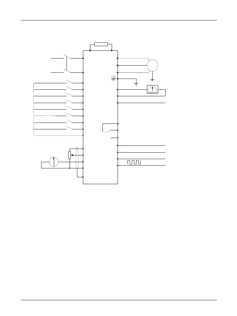
Diagram 3-8 Diagram of wiring for basic running
Applicable inverter: MINI-S-2S0007M-2S0015M
Remarks:
1.--AI2 is used to select voltage or current signal input, switched by the JP1 on the
control panel.
2.--AO1 is used to select Output voltage or current signal, switch by the JP1 on the
control panel.
3.--DI6 Terminal is used to distinguish high speed pulse signal, but it is non-standard
function, should make special description during ordering.