BACnet MS/TP Option Board OPTCJ for 9000X Drives User Manual
2-4
For more information visit:
www.EatonElectrical.com
MN04012006E
August 2006
Bus Biasing
Bus biasing is recommended to ensure fault free communication between all of the devices
on RS-485. Bus biasing ensures that the bus is at the proper potential when no device is
transmitting. Without biasing, faulty messages can be detected when the bus is in idle state.
RS-485 bus state should be within +200 mV to +7V or -200 mV to -7V. Illegal bus state is from
-200 mV to +200 mV.
Table 2-1: Bias Resistor Size vs. Number of Node
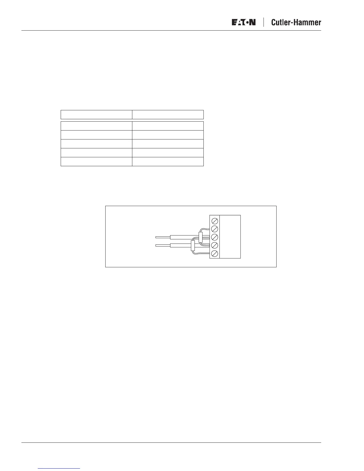
Fail Safe Biasing in OPTCJ Option Board
Connect biasing resistors between pins #2 and #4 as well as pins #3 and #5 as shown in
Figure 2-7
.
Figure 2-7: Biasing Resistor Connections
Matters related to this are discussed in the application note
Failsafe Biasing of Differential
Buses
(an-847.pdf) published by National Semiconductor (www.national.com).
Number of Nodes Bias Resistance
2 – 5 1.8K ohm
5 – 10 2.7K ohm
11 – 20 12K ohm
21 – 30 18K ohm
31 – 40 27K ohm
Data A
Data B
1
2
3
4
5

 Loading...


