XS series operating manual
XS user manual v0.55 - 34 -
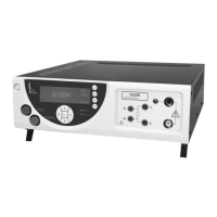
Rear panel description
ELECTRIC S HOCK HAZARD EXISTS WHEN PANEL IS REMOVED. SERVICING TO QUALIFIED SERVICE P ERSONNEL
ONLY. CLASS 1 DEVICE. ROTECTIVE EARTH R EQUIRED D ISCONNECT POWER SUPPLY BEFORE SERVICING. FOR
CONTINUED PROTECTION AGAINST FIRE HAZARD, REPLACE THE FUSES IN RELATION WITH THE USER MANUAL.
ATTENTION !
IL Y A UN RISQUE DE CHOC ELECTRIQUE LORSQUE LE CAPOT EST ENLEVE, LA MAINTENANCE DOIT ETRE FAIT E PAR
DU PERSONNEL QUALIFIE. APPAREIL DE C LASSE 1. TERRE D E PROTECTION OBLIGATOIRE. DECONNECTER TOUTE
SOURCE D’ALIMENTATION AVANT TOUTES INTERVENTIONS DE MAINTENANCE. POUR ASSURER LA PROTECTION
CONTRE LES RISQUES DE FEU, REMPLACER LES FUSIBLES EN SE RAPPORTANT A LA NOTICE.
REMOTE CONTROL
TELECOMMANDE
Fig 5.3
The rear panel includes the following areas :
Z8 Mains power input connector with voltage selector (115V/230V).
Z9 LCD contrast adjustment potentiometer.
Z10 15 points female sub-D connector for remote trigger accessory connection .
Z11 9 points female sub-D connector for RS232C interface.
Z12 Area for the output of the cables in the REAR PANEL OUTPUT option.
Z13 24 points connector for IEEE-488-2 interface.
Z14 10 points screw terminal for safety loop connection.
Z15 10 points screw terminal for PLC connection.
Z16 25 points female sub-D connector for Leakage current measurement function.
Z17 RJ45 connector for ETHERNET interface.
Supplied accessories
1 operating manual ( CD )
1 power cord (SE1)
3 x 10 pts screw terminal with pre-wired safety loop.
1 return cord CO175
 Loading...