MAINTENANCE
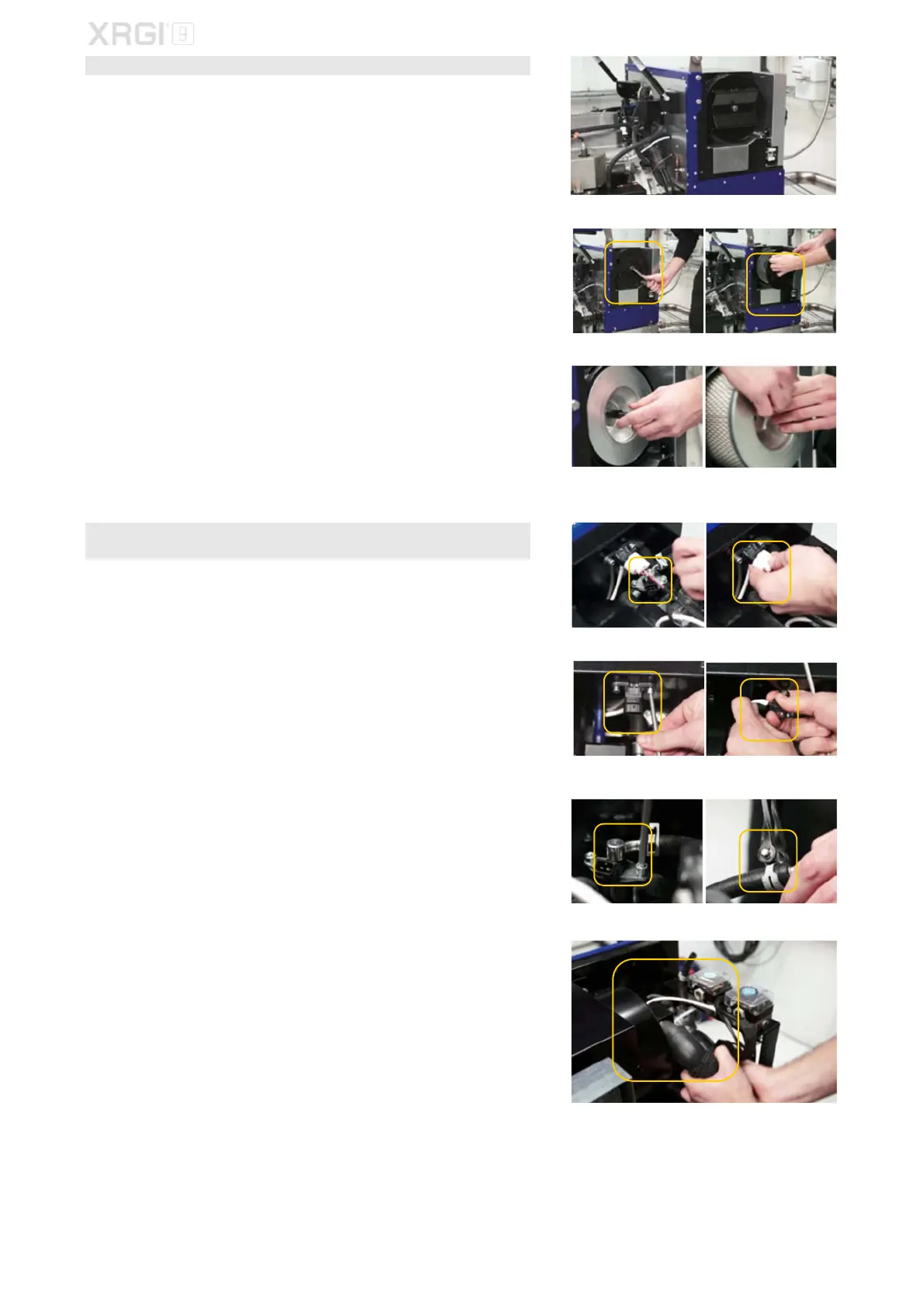
STEP 4 – AIR FILTER
Loosen the screws of the rear cover of the Power Unit with a 3 mm Allen
screwdriver and remove the rear cover.
Loosen the fixing bolt on the air filter cover by a 17 mm open-end spanner
and remove the cover.
Loosen the fixing bolt on the air filter by a 17 mm open-end spanner and
pull the air filter off the threaded rod.
Install the new air filter and put the air filter cover back on − tighten the bolt
by a torque wrench with a 17 mm socket insert.
Torque: 5 Nm.
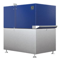
STEP 5 – INJECTOR, ZERO PRESSURE HOSE, VACUUM FILTER & VACUUM
SENSOR
Remove the plug from the injector and vacuum sensor.
Unscrew the vacuum sensor by a 5 mm Allen screwdriver and pull off the
zero pressure hose.
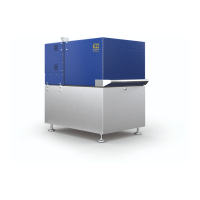
Remove the 2 Allen screws on the injector by an 5 mm Allen screwdriver
and carefully pull the injector from the intake socket.
Loosen the hose clamp by a hose clamp pliers from the gas hose and pull
the injector from the gas hose.
Remove the 2 hose clamps by a hose clamp pliers from the MGB hose and
pull it from the intake socket.
Fig. 5.12
Fig. 5.13 Fig. 5.14
Fig. 5.15 Fig. 5.16
Fig. 5.17 Fig. 5.18
Fig. 5.19 Fig. 5.20
Fig. 5.21
Fig. 5.22
Fig. 5.23