PREVENTIVE MAINTENANCE OF THE WEAR PARTS
Fig. 8.07
Fig. 8.08
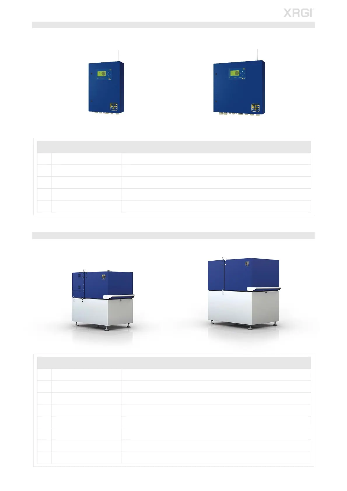
STEP 2 – IQ-CONTROL PANEL
iQ10-Control Panel iQ15/20-Control Panel
With the iQ-Control Panel switched on:
POS COMPONENT DESCRIPTION
1 Transient protection Inspect the transient protection for correct function.
2 Display
Inspect the display of the display board and the current meter for correct function and
condition.
3 Fan Inspect the fan for correct function.
4 Soft starter/Smart Starter
TM
Inspect the soft starter/Smart Starter
TM
for correct function.
5 Terminals Switch of the iQ-Control Panel and retighten all terminals in the iQ-Control Panel.
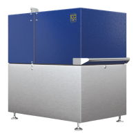
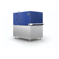
STEP 3 - POWER UNIT
XRGI
®
6/9 Power Unit XRGI
®
15/20 Power Unit
POS COMPONENT DESCRIPTION
1 Safety temperature limiter Inspect the safety temperature limiter for correct function and wear to the capillary tubes.
2 Stepper motor Inspect the stepper motor for correct function.
3 Pressure gauge Inspect the flue gas and vacuum pressure gauge for correct function.
4 Cable harness Inspect the cable harness for correct function and wear.
5 Pressure loss Check the exhaust heat exchanger/vibration damper for pressure loss.
6 Vacuum During system operating, check the oil sump for vacuum.
7 Catalyst Check the catalyst for correct function.
8 Engine/generator mount Visual inspection of the engine/generator mount.
Fig. 8.05
Fig. 8.06