Chapter 5
| Switch Management
Understanding the Switch Status LEDs
– 25 –
Understanding the Switch Status LEDs
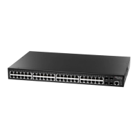
The switch includes LED indicators on the front panel that display system and port
status. Understanding the LED states will help you monitor switch operation and
alert you to any problems.
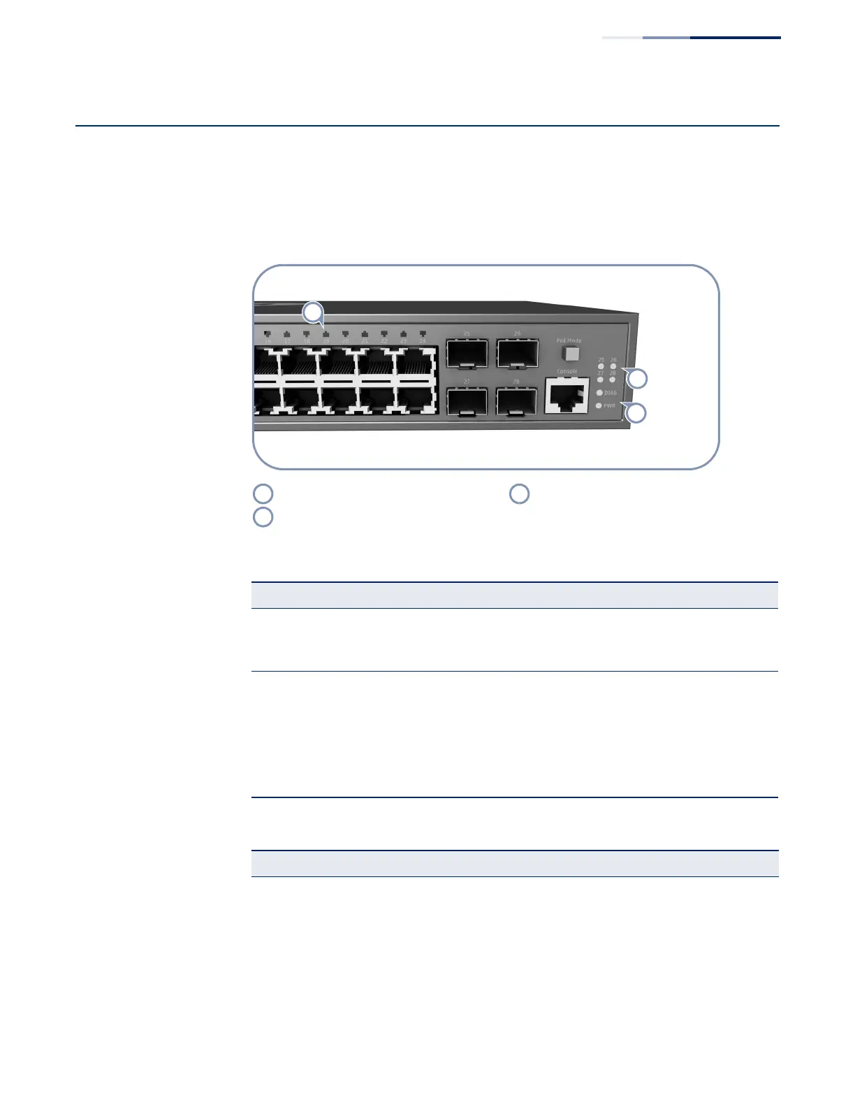
Figure 11: System and Port Status LEDs
(
Ports 1-24 Link/Activity LEDs. System status LEDs.
Ports 25-28 Link/Activity LEDs.
Table 4: System Status LEDs
LED Condition Status
PWR On Green Internal power operating normally.
Off No AC power is connected or the internal power supply
has failed.
DIAG
(Diagnostic)
On Green The system diagnostic test has completed successfully.
On Amber System diagnostic in progress or the PoE button is pressed
down.
Blinking Amber The system self-diagnostic test has detected a fault.
Blinking Amber and
Green
The switch system is booting up.
Table 5: Port Status LEDs
LED Condition Status
1000BASE-T RJ-45 Ports (1-24)
Link/Activity On/Blinking Amber Port has a valid 10/100 Mbps link. Blinking indicates
traffic on the port.
On/Blinking Green Port has a valid 1000 Mbps link. Blinking indicates traffic
on the port.
Off The link is down.