Chapter 5
| Switch Management
How to Connect to the Console Port
– 27 –
The following table describes the pin assignments used in the console cable.
The serial port’s default settings are as follows:
◆ Default Baud rate—115200 bps
◆ Character Size—8 Characters
◆ Parity—None
◆ Stop bit—One
◆ Data bits—8
◆ Flow control—None
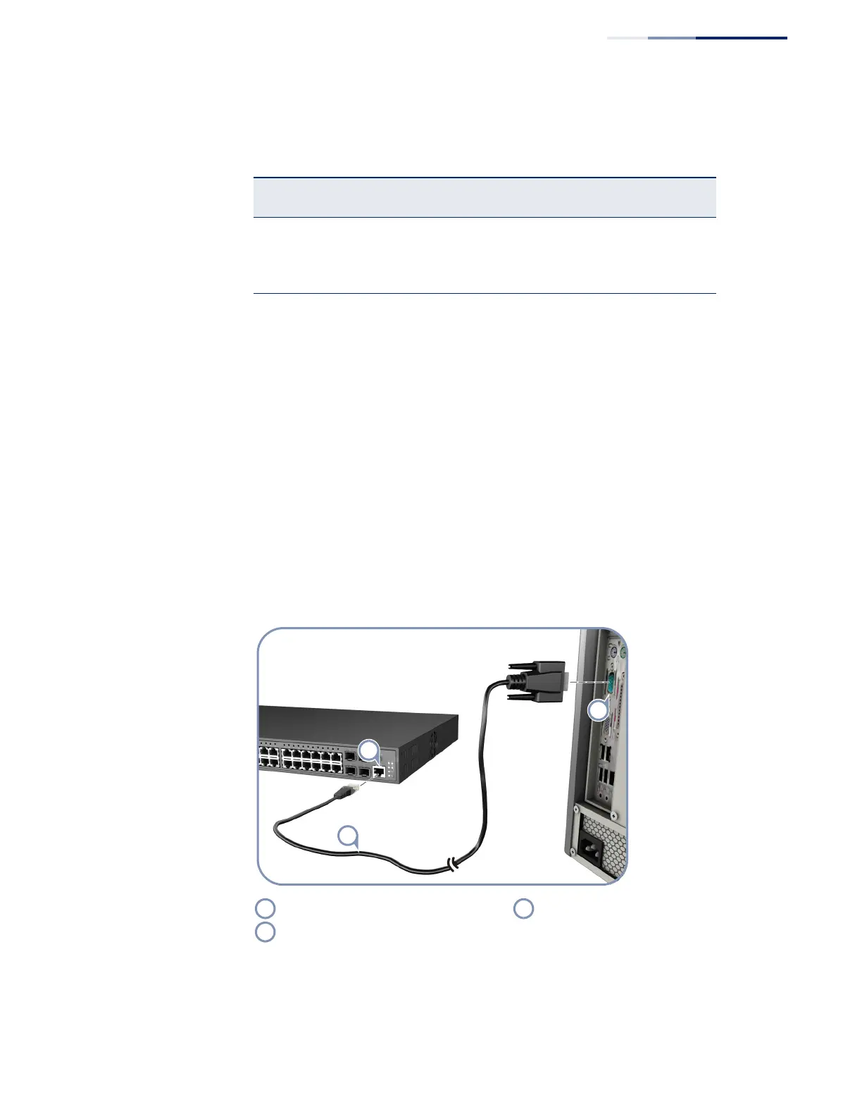
Figure 13: Console Port Connection
Table 6: Console Cable Wiring
Switch’s RJ-45
Console Port
Null Modem PC’s 9-Pin
DTE Port
6 RXD (receive data) <--------------------- 3 TXD (transmit data)
3 TXD (transmit data) ---------------------> 2 RXD (receive data)
4,5 SGND (signal ground) ----------------------- 5 SGND (signal ground)
No other pins are used.
Switch’s Console port. RJ-45 to DB-9 console cable.
PC’s DB-9 COM port.