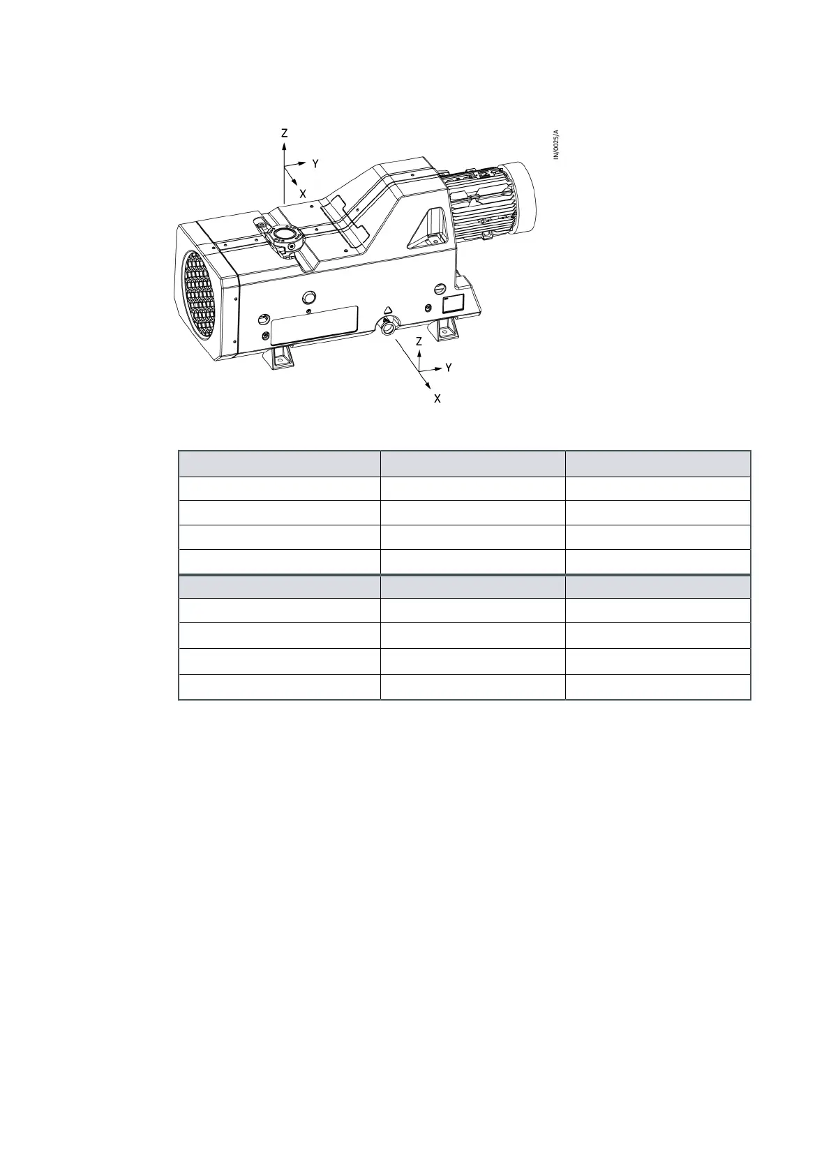
Figure 7 Maximum permissible ange loads
Table 5
Maximum permissible ange load
Maximum force Pump inlet Pump outlet
F
X
±892 N ±446 N
F
Y
±1070 N ±356 N
F
Z
±1338 N ±290 N
F
R
±1931 N ±640 N
Maximum moment Pump inlet Pump outlet
M
X
±476 Nm ±115 Nm
M
Y
±952 Nm ±231 Nm
M
Z
±721 Nm ±177 Nm
M
R
±1285 Nm ±313 Nm
7.4 Connecng cooling-water
(Only for water cooled version)
1. Use G1/2 male pipe ngs to t the cooling-water supply and return hoses.
2.
Remove the blanking plugs from the cooling-water inlet and outlet.
3.
Connect your water return hose to the cooling-water-outlet and connect your water
supply hose to the water-cooling inlet.
4.
Turn on the cooling-water supply.
5.
Inspect the water hoses, pipelines and connecons and check that there are no leaks.
Page 27
A41802880_C - Installaon
 Loading...