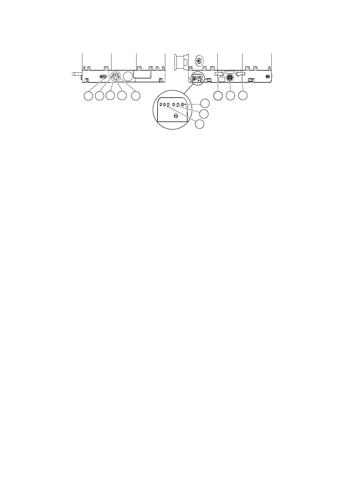
Figure 27 Controller view
Normal
Status
Alarm
Rx
Tx
CAN
Status
CS/5036/A
1
2
3
4
5
9
10
11
6
7
8
1. Bearing LED (indicates when bearing
servic
e is recommended)
2. Standby increase buon
3. RS485/CAN/RS232 slide switch
4. USB connector 5. Standby speed decrease buon
6. Pump status LEDs 7. Serial receive/transmit LEDs
8. CAN status LED 9. nEXT pump power supply interface
10. Accessory connector 11. nEXT pump logic interface
1. Bearing LED (indicates when bearing
service is recommended)
2. Standby increase buon
3. RS485/CAN/RS232 slide switch
4. USB connector 5. Standby speed decrease buon
6. Pump status LEDs 7. Serial receive/transmit LEDs
8. CAN status LED 9. nEXT pump power supply interface
10. Accessory connector 11. nEXT pump logic interface
06/2021 - ©Edwards Limited
Page 30300872820_002_C2
B8J203880_C
300872820_002_C2 - Service counter reset