▪ will open when the normal signal becomes acv
e (pump at speed)
▪ will close when you select the stop buon or if there is a fault condion
The reacon me will be in line with the valve selecon and the output signal is 24 V d.c.
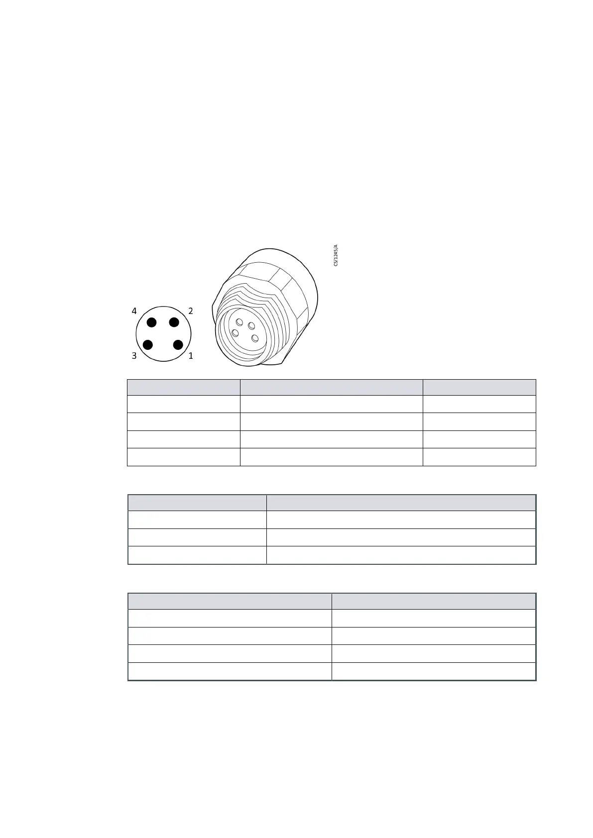
Refer to Figure: Valve connector for polarity of the connector pins when the connector is
energized.
The auxiliary connector is regulated to 24 V d.c. to control the accessories. If the
auxiliary load current exceeds the value in Table: Auxiliary load currents, the output will
shut down to protect the pump controller. Refer to Table: Recommended mang plugs
for the recommended mang plugs.
Figure 3 Valve connector
Pin number Signal Polarity
1 Valve 1 - Control output Posive
2 Valve 2 - Control output Posive
3 Valve 1 - Return Negave
4 Valve 2 - Return Negave
Table 1
Auxiliary load currents
Descripon Data
Connector plug Phoenix part number SACC-DSI-M 8FS-4CON-M12/0.5
Voltage output 24 V d.c. -25%, +10% (18 V d.c. to 26.4 V d.c.)
Output power 2 Channels with 4 was per channel
Table 2
Recommended mang cable
Mang connector cable Phoenix part number
Screw connecon, straight SACC-M 8MS-4CON-M-SW
Solder connecon, straight SACC-M 8MS-4CON-M
Screw connecon, right angle SACC-M 8MR-4CON-M-SW
Solder connecon, right angle SACC-M 8MR-4CON-M
2.4 Logic interface
The logic interface is designed to support the serial control, the parallel control, monitor
and operate through one connector.
05/2021 - ©Edwards Limited
Page 11A90301880_C
A90301880_C - General descripon
 Loading...


