The so-s
tart mode can be invoked following a power outage or disconnecon of power
from the pump.
Table 12
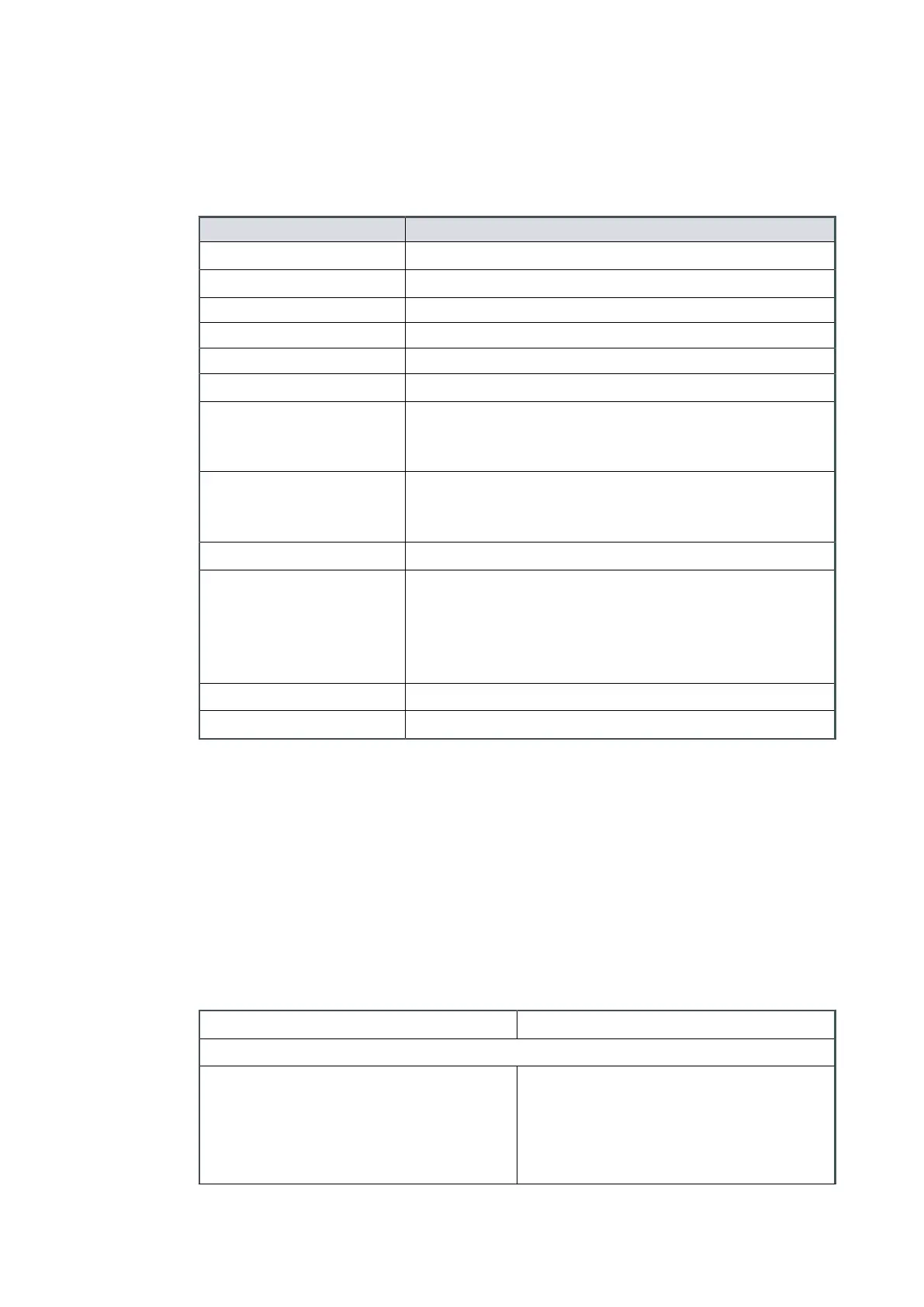
LED indicators
Refer to Figure: Interface control panel for LED locaons on the pump dashboard.
Descripon Funcon
Power indicator Indicates that electrical mains supply to the pump is ON.
Run indicator Indicates that the pump is running.
▪ LED connuously ON ▪ Pump runs at full speed
▪ LED ashing ▪ When changing speed
▪ LED OFF ▪ Pump is not running
Standby mode indicator Indicates that the standby mode has been selected.
Standby speed increase in-
dicator
The indicator will blink with every short push of the
standby speed increase buon. The indicator will remain
ON when maximum standby speed has been reached.
Standby speed decrease
indicator
The indicator will blink with every short push of the
standby speed decrease buon. The indicator will remain
ON when minimum standby speed has been reached.
Auto-run indicator Indicates that the auto-run mode has been selected.
Standby indicator LED
Once the standby funcon is selected the run indicator
will ash at 50% duty while the rotaonal speed is
changed. Once steady state running speed has been
reached both the run speed and standby indicators will
be illuminated.
Service indicator Indicates that a service interval has been reached.
Alarm indicator Indicates an alarm has been triggered.
6.3 Logic interface data
The pumps have a 15-way D-type logic interface connector located on the user interface
panel (Figure: nXRi pumps, (6)). The logic interface connector can be plugged directly
into the 200 W Turbo Instrument Controller (TIC) with an nXRi TIC cable and in
conjuncon with controller extension cables.
For Turbo controller, or Turbo and Acve Gauge controller (TAG), a suitable connector
mang half must be used (not supplied) to connect the nXRi pump to the customer
control system. Refer to and Table: Logic interface pins for the electrical connecons.
Table 13
Interface technical data
Connector* 15-way D-type (male)
Start, serial enable and remote enable:
▪ Enable control voltage: low (closed)
▪ Disable control voltage: high (open)
▪ 0 to 0.8 V d.c. (l
OUT
= 0.55 mA
nominal)
▪ 4 to 26.4 V d.c. (internal pull-up to a
Thevenin equivalent circuit: 5.3 V and
11 kOhms nominal)
05/2021 - ©Edwards Limited
Page 29A90301880_C
A90301880_C - Operaon
 Loading...


