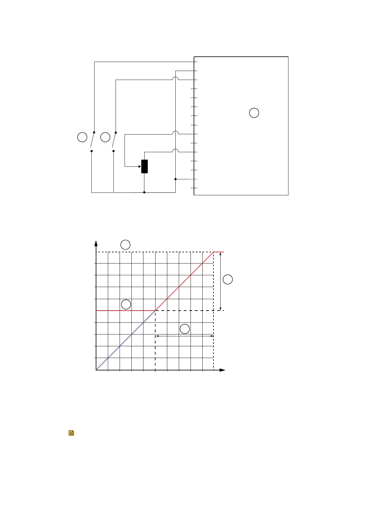
Figure 14 Logic interface c
onnecons - analogue speed control
CS/1044/B
1 = Analogue speed enable input
2 = 0 V Control reference
3 = Start/ Stop control input
4
5
6
7
8
9 = Analogue speed control input: 0 - 10 V
10
11 = +10 V Analogue reference
12
13
14 = Remote enable input
15
1 2
3
1. Analogue control switch 2. Start switch
3. nXRi pump logic interface
1. Analogue control switch 2. Start switch
3. nXRi pump logic interface
Figure 15 Analogue speed control
(%)
(V)
1 98765432 10
90
80
70
60
50
40
30
20
10
100
1
2
4
3
CS/1045/B
1. Upper speed clamp - Maximum standby
seng = 250 Hz
2. Lower speed clamp - Minimum standby
speed seng = 125 Hz
3. Acve speed range - 50.00 % t
o 100.00 %
(125Hz to 250 Hz)
4. Acve Voltage range - 5.00 V to 10.00 V
1. Upper speed clamp - Maximum standby
seng = 250 Hz
2. Lower speed clamp - Minimum standby
speed seng = 125 Hz
3. Acve speed range - 50.00 % to 100.00 %
(125Hz to 250 Hz)
4. Acve Voltage range - 5.00 V to 10.00 V
Note:
0.1 V = 1% of de
fault run speed.
Voltages below 5 V will result in a clamped speed of 50% of full speed.
05/2021 - ©Edwards Limited
Page 33A90301880_C
A90301880_C - Oper
aon
 Loading...


