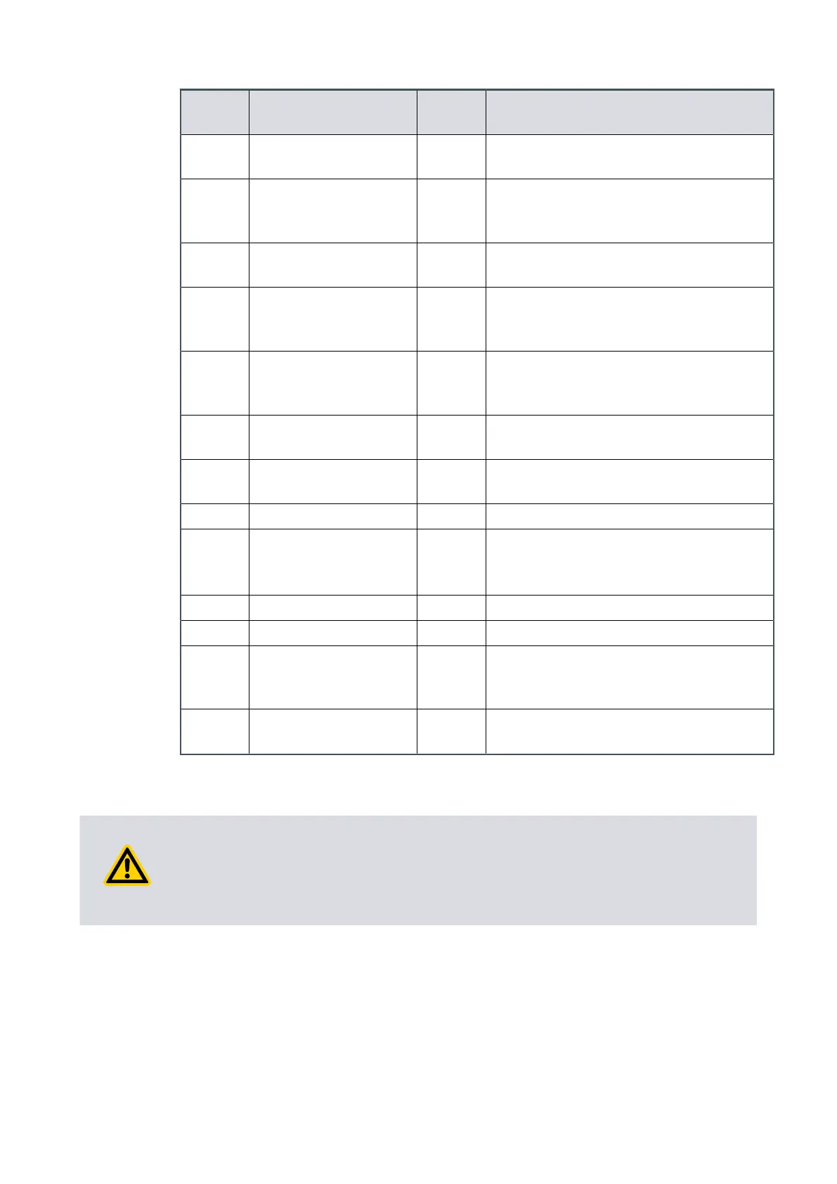
Pin
number
Signal Polarity Use
3 Start/Stop – control in-
put
- Connect to pin 2 (0 V) to start the pump
s
ystem.
4 Standby – control in-
put/serial-RX/RS-485 A-
- Connect to pin 2 (0 V) to enable standby
speed when the serial enable control in-
put is inacve.
5 Serial enable – control
input
- Connect to pin 2 (0 V) to enable serial
communicaons.
6 RS-232/RS-485 – control
input
- Default c
onguraon is RS-232 with pin 6
disconnected. Connect to pin 2 (0 V) to
enable RS-485 serial communicaons.
7 Fail – status output/
Serial-TX/RS-485 B+
- Logic high when a fail/fault condion ex-
ists and the serial enable control input is
inacve.
8 0 V control reference - 0 V reference for all control and status sig-
nals listed within this table.
9 Analogue speed – con-
trol input
- 0-10 V analogue input: 0 V = 0% speed;
+10 V = 100% speed
10 Chassis/Screen - Screen
11 +10 V analogue refer-
ence
– Control output
Posive +10 V analogue voltage reference output:
5 mA; unipolar output, diode protected.
12 Chassis/Screen - Screen
13 Not connected - Unused control pin
14 Remote – control input - Connect to pin 2 (0 V) to enable remote
control via parallel or serial control
modes.
15 Normal – status output - Logic low when the pump rotaonal
speed is at normal speed or above.
6.4 Parallel control and monitoring
CAUTION: EMF RISK
Risk of damag
e to equipment. If you use the normal and fail lines to drive the coils of
d.c. relays, include a back EMF suppression diode in parallel with each relay coil to
protect the pump.
Connect the control equipment to the control input pins of the logic interface mang
half
. Refer to Table: Logic interface pins to idenfy the logic interface connector pins. The
control inputs are:
▪ Start
▪ Standby speed
▪ Analogue speed
05/2021 - ©Edwards Limited
Page 31A90301880_C
A90301880_C - Oper
aon
 Loading...


