A. To acv
ate the control inputs, connect the relevant control input (pin 14) to the 0 V
control reference.
B. The NORMAL output can go down up to 100 mA when you control an external
relay coil with an external coil voltage of + 24 V d.c. The external + 24 V voltage
source, must be referenced to the common control voltage of the pump control
system, i.e. pin 2 of the 15-Way D-Type customer interface connector.
Alternavely, if the NORMAL output is connected to + 10 V reference output of the
control system, i.e. pin 11 of the 15-Way D-Type connector, a 4.7 kOhm pull-up
resistor is recommended to be kept in the current rang of + 10 V reference rail.
C. The FAIL output can go down up to 100 mA when you control an external relay coil
with an external coil voltage of + 24 V d.c. The external + 24 V voltage source, must
be referenced to the common control voltage of the pump control system, i.e. pin
2 of the 15-Way D-Type customer interface connector. Alternavely, if the FAIL
output is connected to + 10 V reference output of the control system, i.e. pin 11 of
the 15-Way D-Type connector, a 4.7 kOhm pull-up resistor is recommended to be
kept in the current rang of + 10 V reference rail.
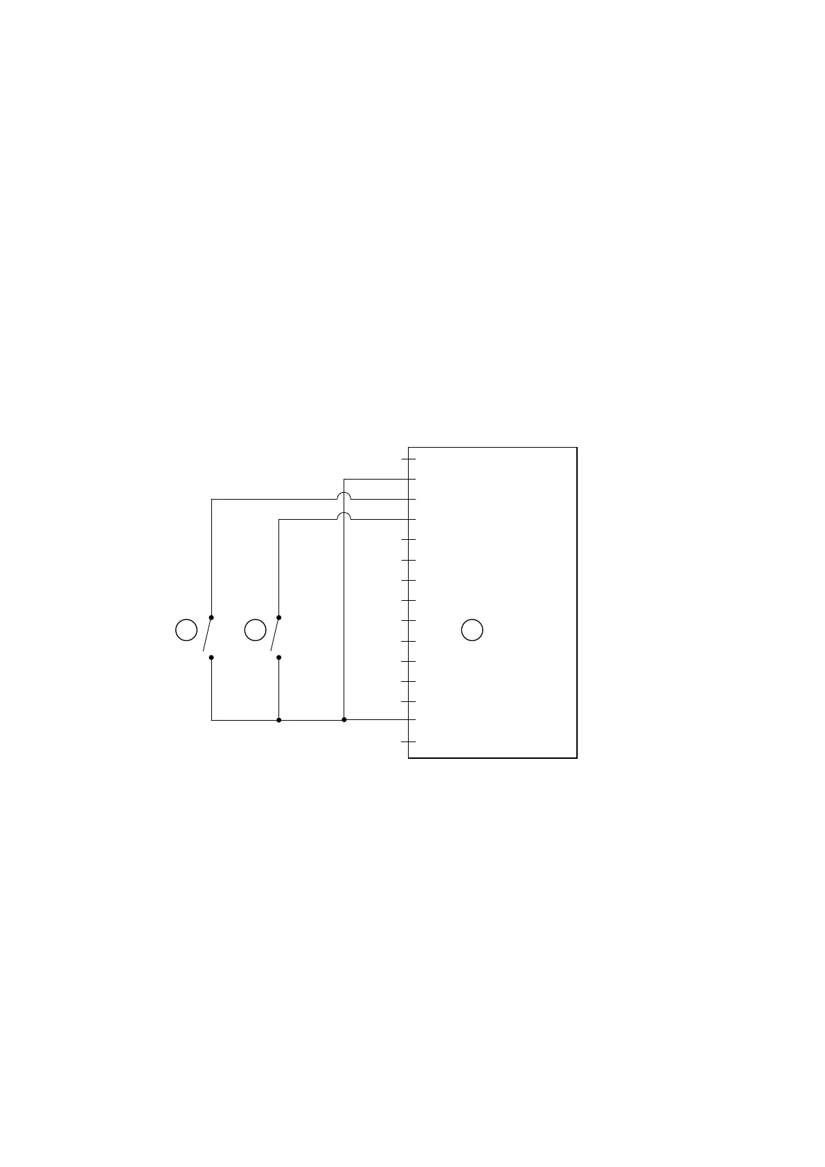
Figure 13 Logic interface connecons - parallel control
CS/1043/B
1 2
3
1
2 = 0 V Control reference
3 = Start/ Stop control input
4 = Standby enable input
5
6
7
8
9
10
11
12
13
14 = Remote enable input
15
1. Start switch 2. Standby switch (oponal)
3. nXRi pump logic interface
1. Start switch 2. Standby switch (oponal)
3. nXRi pump logic interface
6.5 Analogue speed control
The analogue speed input is a pr
ocess control source which enables the nXRi pump to
run at variable operang speeds. This speed control source is an alternave to standby
speed control.
05/2021 - ©Edwards Limited
Page 32A90301880_C
A90301880_C - Oper
aon
 Loading...


