STP-301/451 Series Instruction Manual
10-2
Troubleshooting
< Operation after a Power Recovery>
1) MANUAL operation
The STP pump continues decelerating even after a power recovery. Press the
"START" switch to reaccelerate the STP pump.
2) REMOTE operation
I. When the START signal is input to the REMOTE input terminal at a power
recovery to reaccelerate the STP pump.
II. When the START signal is not input to the REMOTE input terminal after a power
recovery, the STP pump continues the BRAKE operation.
◇ Establish a sequence so that the power can be supplied to the STP control unit
immediately after a power recovery.
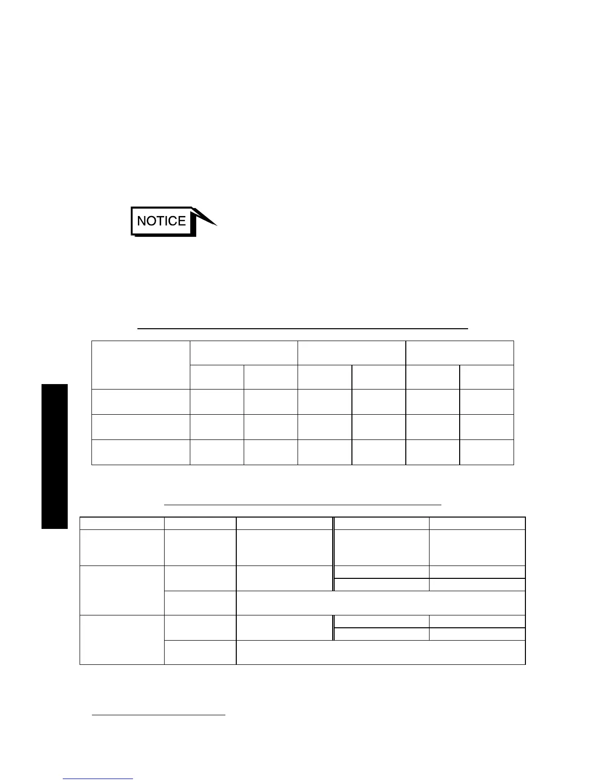
Table 10.1 shows the states of lamps and the REMOTE output signals at a power failure.
Also, Table 10.2 shows the operations of the STP pump after a power recovery.
Table 10.1 States of Lamps and REMOTE Output Signals at Power Failure
LCD LED lamps
REMOTE output
signals (I/O TB1)
Rotational speed
(rpm)
Message Backlight
POWER
lamp
FAILURE
lamp
Power ON
signal
ALARM
signal
20,000 or more
POWER
FAILURE
ON OFF ON OFF ON
17,000 or more and
less than 20,000
POWER
FAILURE
OFF OFF ON OFF OFF
Less than 17,000 OFF OFF OFF OFF OFF OFF
Table 10.2 Operations of the STP Pump after Power Recovery
MANUAL operation REMOTE operation
Rotational speed
(rpm)
Duration of
power failure
STP pump operation
after power recovery
"START" REMOTE
signal input after
power recovery
STP pump operation
after power recovery
Yes Reacceleration
pprox 2 sec or
longer
Deceleration/Stop
No Deceleration/Stop
25,000 or more
Shorter than
approx 2 sec
Continues as before.
Yes Reacceleration Approx 0.02 to
0.14 sec
*1
Deceleration/Stop
No Deceleration/Stop
Less than 25,000
Shorter than
the above
Continues as before.
*1
: A power failure is detected faster the less the number of rotations at the power failure.

 Loading...

