75
8. Bus Remote Interface GPIB / USB / RS-232
This section provides information on the proper use and configuration of bus remote interface.
The USB / RS-232 remote interface is standard on SE series but the GPIB (IEEE-488) interface
option can be substituted for the USB / RS-232 interface. Please refer to the Option section of this
manual for details on the SE SERIES options. The USB / RS-232 interface also uses the same
command set as the GPIB interface for setting of test parameters. However there are many
functions of the GPIB 488.2 interface that are not available through USB / RS-232. The IEEE-488
interface included with SE SERIES conforms to the requirements of the IEEE-488.2 standard.
8.1. RS-232 Interface
This interface provides all of the control commands and parameter setting commands of the GPIB
interface with the exception of some of the 488.2 Common Commands and SRQ capability. All
commands can be found in section 8.4. USB / RS-232/GPIB Command List. The identification
command *IDN and the Status Reporting commands are also available through RS-232.
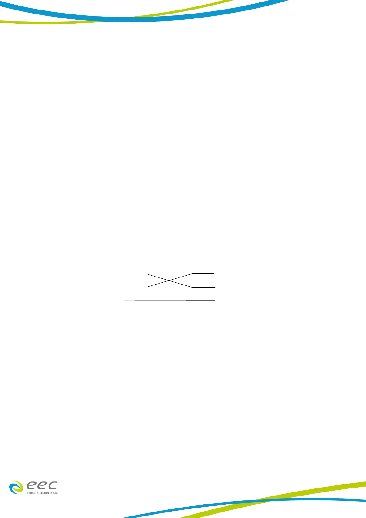
8.1.1. RS-232 Connector
The RS-232 cabling should be configured as follows for a 9-pin serial port interface
8.1.2. Communications Port Configuration
The COM port should have the following configuration:
9600 baud
8 data bits
1 stop bit
No parity
This interface does not support XON/XOFF protocol or any hardware handshaking. The controller
should be configured to ignore the handshaking lines DTR (pin 4), DSR (pin 6) CTS (pin 8) and RTS
(pin 7). If the port cannot be configured through software to ignore these lines the handshake
lines should be jumpered together in two different sets. Pins 4 and 6 should be jumpered together
and pins 7 and 8 should be jumpered together at the controller end of the cable.