On-board troubleshooting
12
4.1.2 Preparations
You may need the following tools and devices:
A Pozidrive Pz0 or Pz1 screwdriver to loosen the screws on the module.
An oscilloscope
A multimeter
4.2 Normal situation
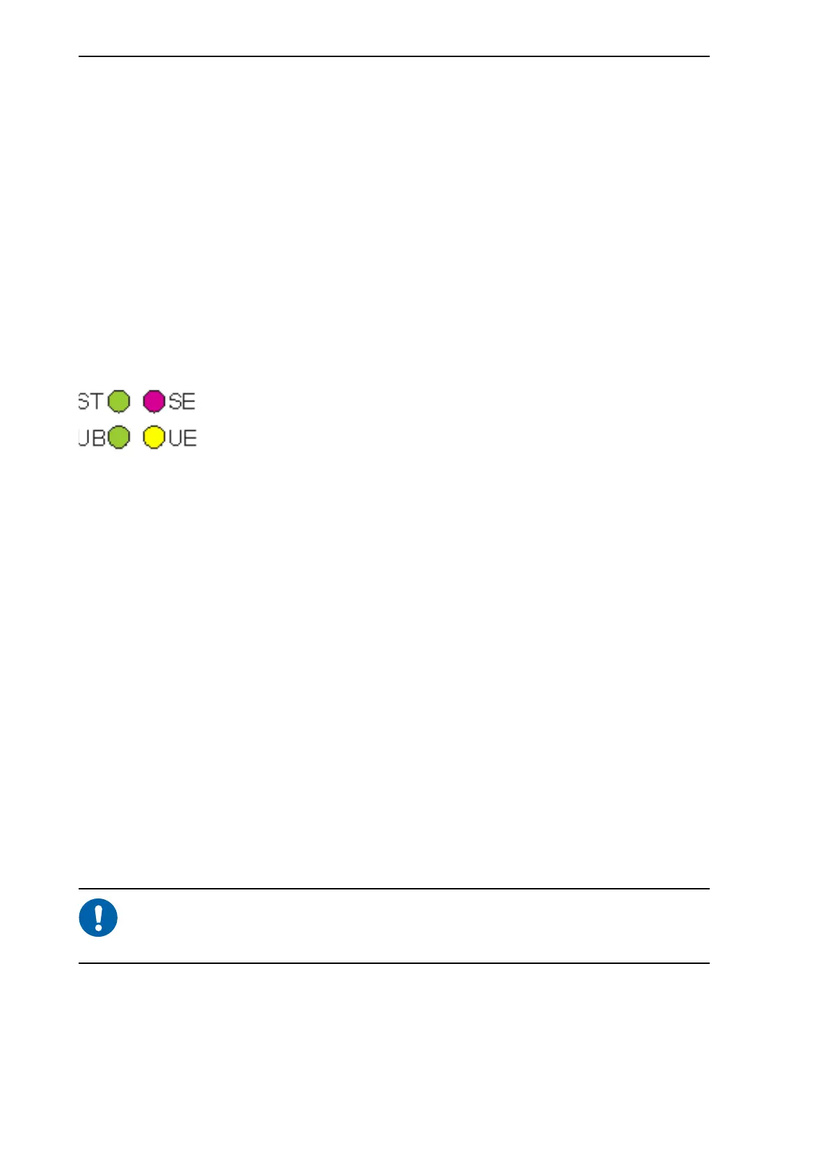
The front panel of the MVB contains four LEDs: two green, one red and one yellow.
You can detect the status of the MVB module by looking at the LEDs in the front panel.
The following picture shows the four LEDs on the module and their names.
Figure 4.1: MVB LEDs
When the LEDs are on, it means the following:
In a normal situation, the green ST LED is on and the green UB LED is blinking. If the
red SE LED or the yellow UE LED is on, there is an error situation. For troubleshooting,
see page 13 (Yellow LED blinking) and page 19 or page 19 (Red LED on/blinking).
During the module start-up, the red SE LED and yellow UE LED are on for
a moment and then go off. This is part of the normal start-up procedure and
does not indicate an error.
4.3 Error situations
If the Multifunction Vehicle Bus does not function normally, the problem can be either
in the MVB module or in the bus itself. If the problem is with the bus, you can only
troubleshoot it on board the train. If the problem is with the module, you need to remove
ST (green):
STATUS
Module hardware has started.
UB (green):
UNIT BUS
Principal activity of the module is OK; the module is transmitting data.
UE (yellow):
UNIT ERROR
Problems with the principal activity of the MVB module. This means that the
module has detected a network bus related error or a data transmission
error.
SE (red):
SYSTEM
ERROR
No principal activity in the MVB module. This means that the module is not
able to provide any kind of bus service.