Troubleshooting with software
38
EXPLANATION
Use this command to set the addressing mode to absolute or logical. This command is
needed before RM - Read Memory (page 39) and SM - Set Memory (page 41)
commands.
When you need to read the module memory or write to it, you can use two addressing
modes.
Absolute addressing refers to the complete 1 MByte physical address space of the
Z180 microcontroller. Logical addressing refers to the 16-bit address space directly
accessible by the MPU.
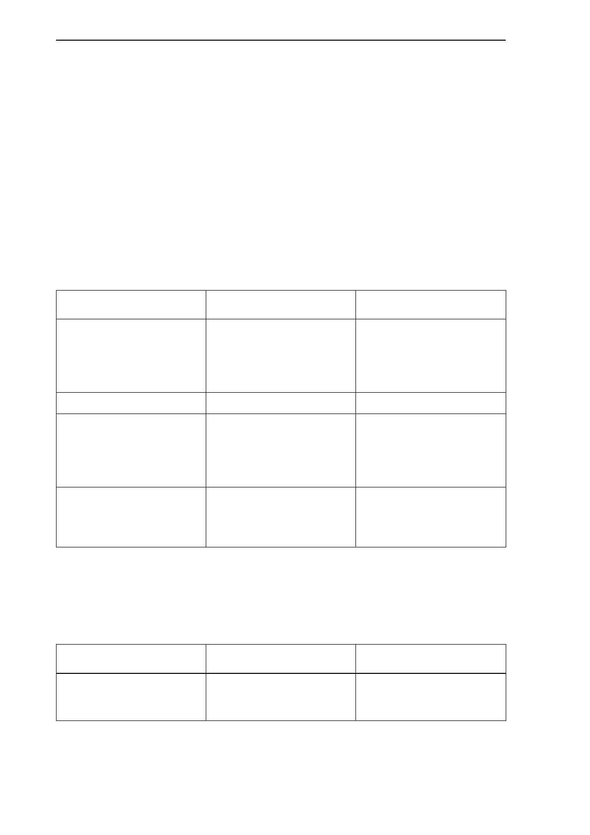
The following table contains a memory map for the complete 1 MByte physical address
space.
Table 5.4: Addresses and contents for the physical address space
When you want to read or modify software version-specific data, use logical
addressing. The following table contains a memory map for the 16-bit logical address
space.
Table 5.5: Addresses and contents for the logical address space
Address range in absolute
addressing mode
Memory contents Address in logical
addressing mode
0x00000 - 0x0FFFF Executable code image in
RAM. During reset, the
system reads this image
from on-board Flash
memory.
0x0000
0x10000 - 0x12FFF Data area in RAM. 0xD000
0x80000 - 0xBFFFF Shared memory visible to
Zilog and to the VME master
CPU (through VME bus).
When ASIC is in reset, Traffic
Memory is visible.
0xB000-0xCFFF (through an
adjustable 8 KB window)
0xC0000 - 0xFFFFF The upper side of Traffic
Memory, Shared Memory or
FLASH visible to Zilog and
VME master CPU.
0xB000-0xCFFF (through an
adjustable 8 KB window)
Address range in logical
addressing mode
Memory contents Address in absolute
addressing mode
0x0000 - 0xAFFF Executable code image. Overlaps the corresponding
area in physical address
space.