56
Marking wires
In a twisted pair, the individual wires must be identified in the following way:
For Line A : A. Data_P and A.Data_N
For Line B: B. Data_P and B. Data_N
The individual wires of the cable must be clearly marked, and the marking must be
maintained at all connection and splicing points.
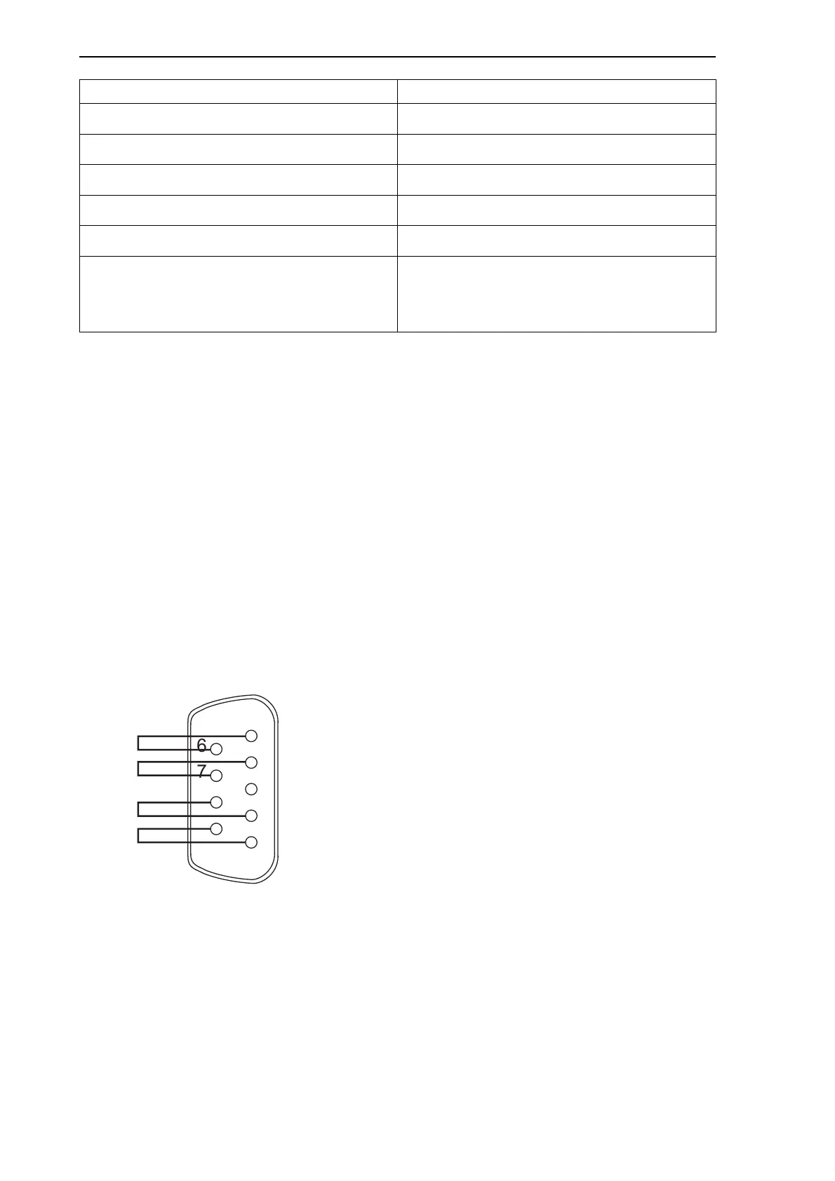
Termination
A cable segment must be terminated electrically at each end by a terminator.
The connector shall be strapped by connecting pin 1 to pin 6, pin 2 to pin 7, pin 4 to pin
8, and pin 5 to pin 9.
The following picture presents an MVB (EMD) terminator.
Figure A.1: MVB EMD terminator
Capacitive unbalance to shield < 1.5 pF/m at 1.0 BR
Crosstalk rejection > 45.0 dB at 0.5–2.0 BR
Transfer impedance of shield < 20 mOhm/m at 20 MHz
Differential transfer impedance of shield < 2 mOhm/m
Resistance of connectors < 10 mOhm
Transfer impedance of connectors < 20 mOhm at 20 MHz between one pin and
shield
< 2 mOhm between two pins
Variable Specification
1
6
2
3
4
5
7
8
9