31
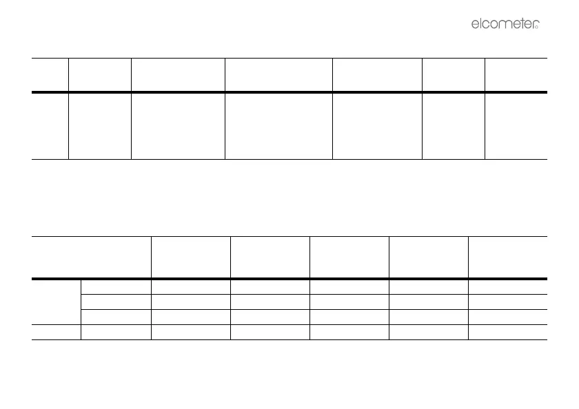
Table 1: Probe part numbers
Scale Range
Accuracy
a
Resolution
Replacement
probe types
b
Original
probe no.
Current
probe no.
F1 0 - 1500 µm ±3% or ±2.5 µm
±1% or ±2.5 µm
c
1 µm
Below 20 µm, 0.1 µm
F1 Standard
F1 Right Angle
F1 Telescopic
T3457286-
T3457650-
T3457651-
T34515844
T34515845
T34515846
0 - 60 mil ±3% or ±0.1 mil
±1% or ±0.1 mil
c
0.1 mil
Below 1 mil, 0.01 mil
a. Whichever is the greater
b. Separate probe versions only
c. Whichever is the greater when calibrated close to the thickness to be measured.
Table 2: Probe capabilities
Probe Type
Minimum
Convex Surface
Diameter
Minimum
Concave
Surface Radius
Headroom
Minimum
Sample
Diameter
Cal Foil Value
a
Separate
F1 4 mm (0.16") 25 mm (0.98") 85 mm (3.35") 4 mm (0.16") 250 µm (10 mil)
F1 Right Angle 4 mm (0.16") 25 mm (0.98") 25 mm (0.98") 4 mm (0.16") 250 µm (10 mil)
F1 Telescopic 4 mm (0.16") 25 mm (0.98") 30 mm (1.18") 4 mm (0.16") 250 µm (10 mil)
Integral F1 4 mm (0.16") 25 mm (0.98") 122 mm (4.8") 4 mm (0.16") 250 µm (10 mil)
a. This is the recommended maximum calibration foil value to achieve the specified accuracy under these measurement
conditions.