Do you have a question about the Elcometer 500 and is the answer not in the manual?
Lists all items included in the Elcometer 500 gauge packaging for user reference.
Instructions on updating the gauge firmware via ElcoMaster® for optimal performance.
Step-by-step guide for inserting or replacing the AA batteries in the gauge.
Procedures for powering the Elcometer 500 gauge on and off correctly.
Details on how to properly connect the C1 or C2 probe to the Elcometer 500 gauge.
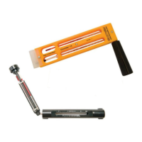
Instructions for attaching and replacing the probe tip, including wear checks.
Guidance on applying probe tip oil to the sensor plate for accurate ultrasonic measurements.
Pre-measurement checks and preparations required before taking readings.
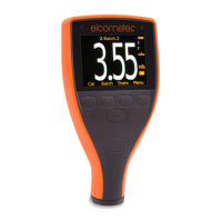
Detailed procedure for obtaining thickness readings in the standard measurement mode.
Instructions for using the scan mode to take rapid measurements over larger surface areas.
How to change the display language of the Elcometer 500 gauge.
Configuration options for screen brightness and timeout behavior.
Customizing the information displayed on the top and bottom halves of the gauge screen.
Details the thickness range the Elcometer 500 can measure on various substrates.
Identifies suitable substrates like concrete, drywall, and plasterboard for measurement.
How to select preferred measurement units such as µm, mm, mils, or inch.
Options for setting the display resolution to 'Low' or 'High' for precise readings.
Procedure for setting upper and lower limits for specific individual measurements.
Guide to setting limits when starting a new data batch.
How to access and apply previously saved limit settings.
Instructions on how to change the names of saved limit memories.
Process for modifying the values of existing saved limits.
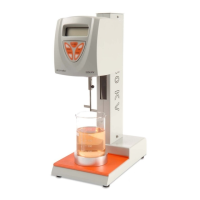
Preparatory steps required before performing gauge calibration.
Step-by-step guide for calibrating using a single known thickness value.
Procedure for calibrating the gauge by entering the coating's sound-velocity.
Instructions on how to save a completed calibration for future use.
Method for calibrating using pre-defined or user-defined coating materials.
Process for restoring the gauge to its default factory calibration settings.
How to test and confirm the accuracy of the current gauge calibration.
Using PIN lock to secure calibration settings on Model T.
Pre-zeroing checks including cleaning the probe surface.
Step-by-step instructions for performing the probe zeroing process.
Displays statistical analysis of readings within a selected batch.
View individual readings with date and time stamps within a batch.
Visualizes batch readings using column bar graphs for trend analysis.
How to use ElcoMaster® software on a PC for data archiving and reporting.
Using ElcoMaster® mobile apps for field data capture and management.
Details on the available C1 and C2 probes, their measurement ranges, and connection.
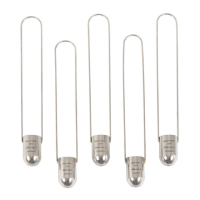
Information on ultrasonic couplant, its importance, and available sizes.
Details and part number for the Elcometer 500 Coating Calibration Mould (CCM).
| Model | Elcometer 500 |
|---|---|
| Type | Coating Thickness Gauge |
| Power Supply | 2 x AA batteries |
| Display | LCD |
| Substrate | Non-ferrous metals |