13
LEDs
TX [Red] Turns on in transmit mode.
∆F [Yellow] The Delta-F LED turnson if
transmit and receive frequencies or modes are
different due to the use of SPLIT, RIT, or XIT.
[Green] Eight LEDs show which functions are
in effect for the Multifunction Controls (pg. 14).
(-) (+) RIT/XITOFFSET If the
offset control is centered, or you tap C LR , the
green LED turnson (offset = 0). Otherwise, the
yellow (-) or (+) LED will be on, indicatingthe
direction of the offset. See RIT , XI T , and CLR .
Front Panel Connectors
PHONES You can use either mono or stereo
headphones at either the front- or rear-panel
headphone jack. Also see AFX (pg. 35).
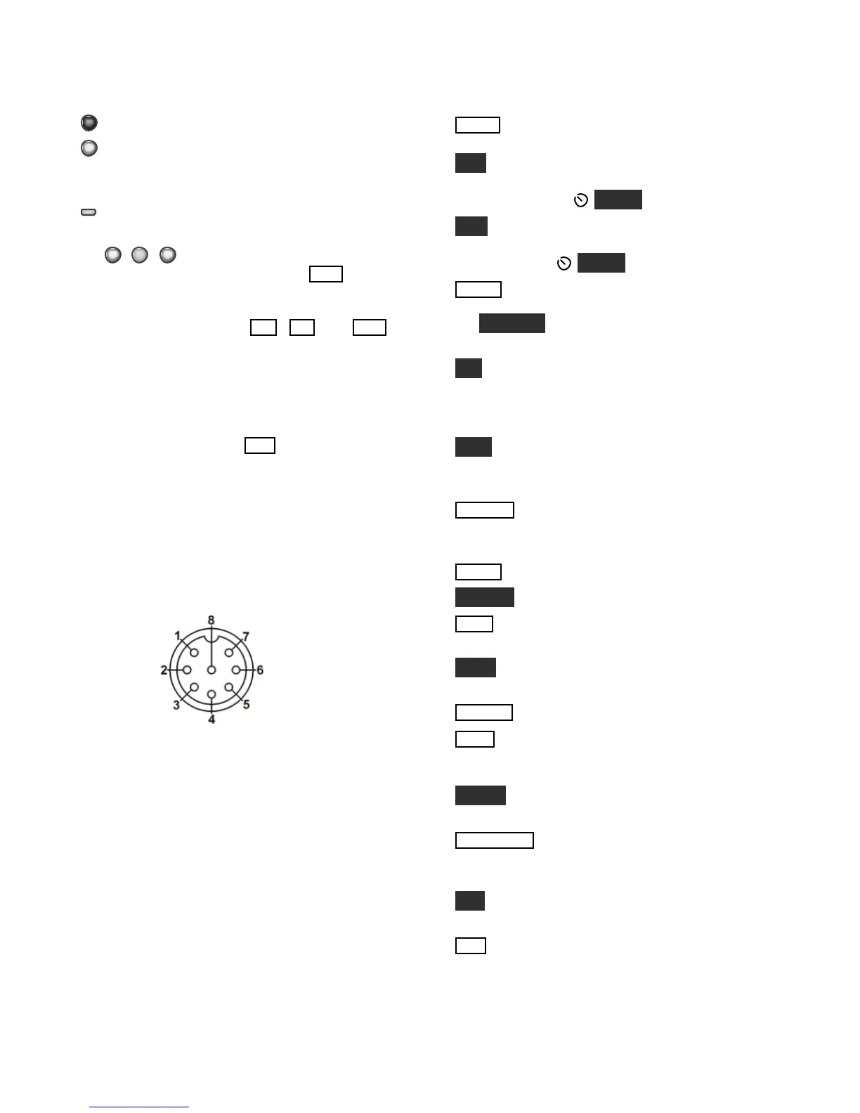
MIC An Elecraft MH2, MD2, Proset-K2, or other
compatible mic can be used (see pinout below). To
select the front- or rear-panel mic, and to turn bias
on/off, use the MAIN:MIC SRC menu entry.
Bias must be turned on for electret mics (e.g. MH2,
MD2, Proset). It must be off for dynamic mics (e.g.
Heil mics using HC4 or HC5 elements).
Mic jack, viewed from frontof K3
1 Mic audio, low-Z (~600 ohms)
2 PTT
3 DOWN button *
4 UP button *
5 FUNCTION button *
6 8V (10 mA max)
7, 8 Ground
* See CONFIG:MIC BTN menu entry (pg. 52)
FP ACC This connector (RJ-45, 6 pins) is located
on the bottom of the transceiver, nearthe VFO B
knob. It is used with accessory devices.
Primary Controls
BAN D Tap the left / right end of this switch to
move to the next lower / higher ham band.
VOX Selects voice-operated or keying-activated
(CW) transmit (VOX icon on), or PTT-controlled
transmit. Also see DELAY (pg. 30).
QSK Selects either full break-in (QSK icon on) or
semi break-in keying, if VOX is selected in CW
mode. Also see D ELAY (pg.30).
MOD E Tapthe left or right end of this switch to
select the operating mode. When DATA is selected,
the DATA MD switch is used to specify DATA-A,
AFSK A, FSK D, or PSK D (pg. 31).
ALT In LSB mode, switches to USB (and vice-
versa). Also selects alternate modes, including:
CW REV, DATA REV, and AM -S (pg. 29). In
FM mode, selects +/- or simplex (pg. 29).
TEST SelectsTX NORM orTX TEST (TX LCD
icon flashing).TX TEST allows you to test keying,
mic level, etc., without actually transmitting.
POWER Turnsthe K3 on or off. Note: To ensure
correct save of operating parameters, turn the
K3 off before turning the power supply off.
MEN U Displays MAIN menu (pg. 21).
CONF I G Displaysthe CONFIG menu(pg. 21).
XMI T Manually-operated transmit. Places the K3
into transmit mode (same as PTT, pg. 26).
TU N E Puts out a carrier at the present power level.
Also TUNEPower Level (pg. 27).
RX AN T Selects the receive antenna (pg. 22).
DISP Shows an alternate display on VFO B,
including time, date, voltage, etc. Use the VFO B
knobto select the desired display (pg. 36).
METER Selects voice transmit bar graph modes:
SWR and RF, or CM P and ALC (pg. 28).
ATU TU N E Placesthe K3 into low-power CW
transmit mode and matchesthe antenna usingthe
KAT3 automatic antenna tuner (pg. 22).
ATU Puts the ATU into normal mode (ATU icon
on) or bypass mode (pg. 22).
ANT Selects ANT 1 or 2 and recalls the last ATU
settings used for that antenna (saved per-band). In
BSET mode with the sub receiver on, selects MAIN
or AUX antenna forthe sub receiver (pg. 37).