41
KANT3
Ant. Input Module
Main RX
Ant 1
KRX3
RX Ant.
KXV3
Sub RX
K2
K1
*
*
SA4
*
Includes C.O.R.
Aux RF
SA1
SA3
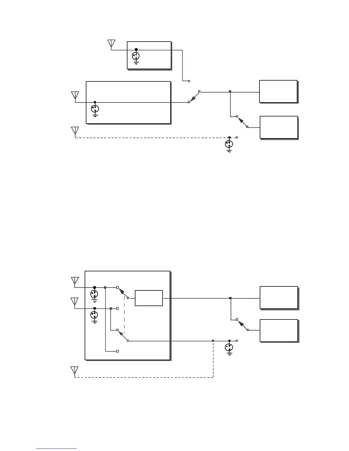
Figure 2. Main/Sub Receiver Routing with KXV3 Installed
K3 with KAT3 ATU
The KAT3 internal ATU, which replaces the KANT3 antenna input module, provides a second SO239 antenna
jack (ANT 2). As shown in Figure 3, relay K3 routeseither ANT 1 or ANT 2 to the main RFpath.The antenna
not routed to the main path (the non-transmit antenna) can optionally be used as the sub receiver’s AUX RF
antenna. This requiresthat the two antennas connected to the KAT3 be well isolated from each other. If not,the
sub receiver’s carrier-operated relay may turn on duringtransmit. If this occurs, you must either move thetwo
antennas farther apart, or not connect the sub receiver to the KAT3.
It may be preferable to connect the sub receiver’s auxiliary RFinput to the AUX RF connector on the rear panel.
A well-isolated receiving antenna can then be used with the sub receiver when required. (See CONFIG:KRX3,
for sub receiver antenna setup.)
Ant 1
Ant 2
KRX3
L-Network
KAT3 ATU
Sub RX
K3
K1
*
SA1
SA2
SA4
*
Includes C.O.R.
Aux RF
Main RX
Figure 3. Main/Sub Receiver Routing with KAT3 Installed