23
Receiver Setup
This section explains howto use basic receiver
controls. Setup for specific operating modes is
described in later sections; see Voice Modes(pg.
28), CW Mode (pg. 30), and Data Modes (pg. 31).
Also see Text Decode and Display (pg. 30) and
Audio Effects (pg. 35).
Receiver Gain Controls
Use AF — SUB (pg. 11) to set the desired main
and sub receiver volume level.There are two
overall audio volume ranges, LO and HI, which can
be selected using CONFIG:AF GAIN.
Usually, both RF — SUB controls will be set
fully clockwise (main and sub receiver RF gain).
You may wish to reduce RF gain to optimize
receiver response to high signal levels or noise.
If the sub RF gain knob has been reconfigured
as squelch for both receivers,then the main RF gain
knob will control RF gain for both receivers. (See
CONFIG:SQ MAIN.)
To improve weak-signal reception, turn on the
preamp using PR E .In the presence of extremely
strong signals, you may wish to use the attenuator
(ATT), or reduce the RF GAIN setting.
Crystal Filter Selection
You can install as many as five crystal roofing
filters in the K3’s main receiver, and another five in
the sub receiver (KRX3, pg. 37).
Bandwidths as narrow as 200 Hz and variable-
bandwidth filters are available, thanks to the K3’s
low first I.F. (intermediate frequency) of 8.215
MHz. See Appendix A for recommended crystal
filter bandwidths for each mode.
To select a crystal filter manually, tap XFIL. The
FL1-FL5 icons show the current selection. This
setsthe DSP passbandto matchthe crystal filter,
and removes any passband shift or lowcut/hicut.
The K3 will also select the most appropriate crystal
filters automatically as you adjust the SHIFT,
WID TH , L O CUT, and H I CUT controls.
Filter Passband Controls
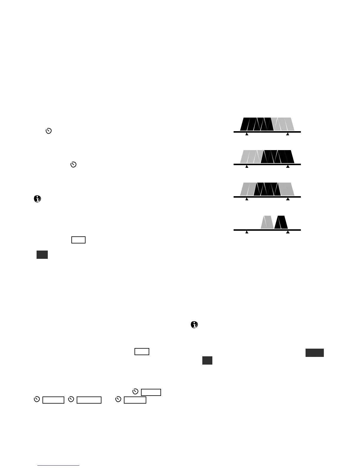
As you rotate the filter controls (shift, width, hicut,
locut), the associated parameter value is shown on
VFO B. The filter graphic shows the width and
location of the passband, as illustrated below. In
these specific examples, segments that turned off as
a result of control movement are shown in gray.
High Cut
Low Cut
Width
Shift
Each passband control has an integral switch. These
are used as follows:
Tappingthe control alternates between the two
primary functions for that control, for example
HICUT andWIDTH. This is indicated by the
two LEDs above each control.
Holding a control activates its secondary
function, labeled below the control.
Tappingor rotating a control shows the present
setting. To see the settings of both knob functions
without changingthem, just tap the control twice.
The secondary functionsof the controls are N OR M
and I /II, described in the following sections.