19
BandOutputs (BAND0-BAND3)
BAND0-3 provide band selection signals. Their
behavior is determined by the CONFIG:KIO3
menu entry. (See tables below.)
BAND0-3 are open-drain outputs. The attached
device must provide pull-up resistors (typ. 2.2K) to
its own supply voltage (usual 5 VDC).
In the tables below, 0 = 0 VDC, and 1 = device
supply voltage.
With CONFIG:KIO3set to NOR, the BAND0-3
outputs are mapped based on the selected HF-6 m
band as shown below. This mapping matches that
of some third-party band decoders. On Transverter
bands, BAND0-3 will all be set to zero.
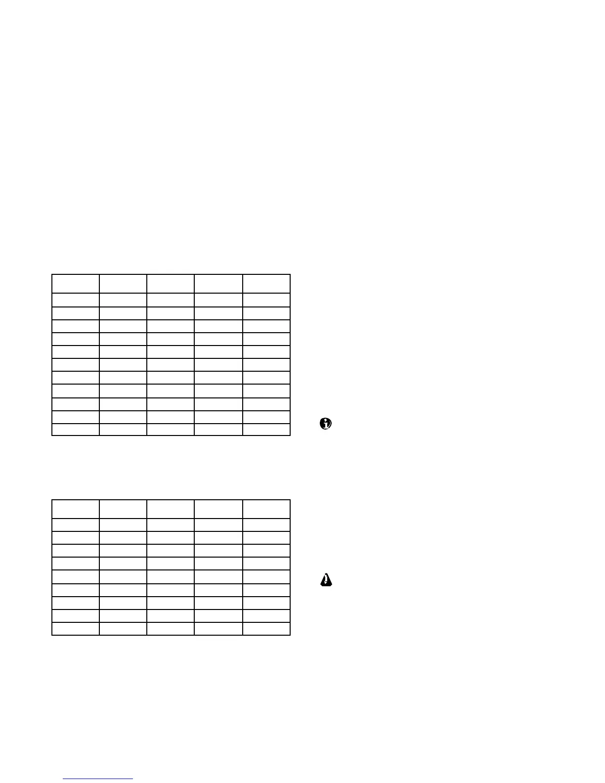
Band BAND3 BAND2 BAND1 BAND0
160 m 0 0 0 1
80 m 0 0 1 0
60 m 0 0 0 0
40 m 0 0 1 1
30 m 0 1 0 0
20 m 0 1 0 1
17 m 0 1 1 0
15 m 0 1 1 1
12 m 1 0 0 0
10 m 1 0 0 1
6 m 1 0 1 0
If CONFIG:KIO3 is set to TRN, BAND0-3 reflect
the parameters of CONFIG:XVn ADR as shown
below. On HF-6 m they’re set to 0.
ADR
BAND3 BAND2 BAND1 BAND0
T RN1 0 0 0 1
T RN2 0 0 1 0
T RN3 0 0 1 1
T RN4 0 1 0 0
T RN5 0 1 0 1
T RN6 0 1 1 0
T RN7 0 1 1 1
T RN8 1 0 0 0
T RN9 1 0 0 1
With CONFIG:KIO3 set to HF-TRN, the
BAND0-3 outputs follow the NOR table when HF-
6 m bands are selected, and the TRN table when a
transverter band is selected.
Transverter Control
Normally, when the K3 isturned on, a 5-VDC logic
signal appears on ACC pin 7 (K3 ON).This could
be used with Elecraft XV transverters as an enable
signal (pin 8 of J6 on the transverter).
However, pin 7 can alternatively be configured as a
transmit inhibit input line for use in multi-
transmitter stations. (See TX INH, below.) In this
case it isnot available as a power-on signal for
Elecraft transverters. Instead, the K3’s 12-VDC
switched output line could be used.
For transverter keying, you can use KEYOUT-LP
signal (pin 10 of the ACC connector) orthe KEY
OUT jack (RCA).
With KIO3 set to TRN or HF-TRN, the DIGOUT0
line (ACC, pin 6) will output 0 V when low power
mode is selected for the current transverter band
(CONFIG:XVn PWR). At all other times,
DIGOUT0 will be floating (Hi-Z).
The K3’s BAND0-2 outputs emulate the
Elecraft K60XV’s XVTR0-2 signals when
CONFIG:KIO3 is set to TRN or HF-TRN.
However, BAND0-2 on the K3 are open-drain
signals, while XVTR0-2 onthe K60XV are TTL.
TX INH (Transmit Inhibit Signal)
Pin 7 of the ACC connector can be configured as a
transmit inhibit input by setting CONFIG:TX INH
to LO=Inh (or HI=Inh). Holding pin 7 low (or
high) will then prevent transmit. An external 2.2 to
10 K pull-up resistor (to 5 VDC) is required.
If TX INH is set to OFF, pin 7 revertsto its
default output function, K3 ON (see above).
Elecraft KRC2 Universal Band Decoder
An Elecraft KRC2 can be used with the K3to
perform station switchingfunctions; it includes sink
and source drivers for all bands. The KRC2 usesthe
AUXBUSrather BAND0-3 (see CONFIG:KRC2
for 6-meter band mapping). Refer to the KRC2
instruction manual for more information.