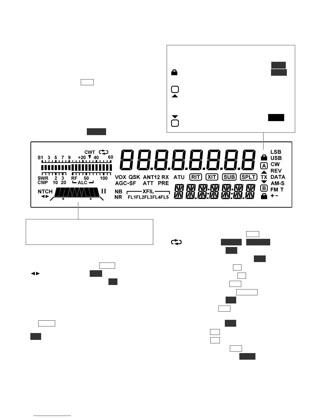
Display (LCD)
Multi-character displays: The 7-segment display
(upper) shows the VFO A frequency. The 13-
segment display (lower) shows VFO B or text.
Bar graph, receive mode: The bar graph normally
acts as an S-meter. If CWT is turned on, the right
half of the S-meter becomes a tuning aid (pg. 36).
Bar graph, transmit mode: The bar graph
normally shows SWR and RF power output. The
RF scale will be either 5 and 10 (low power) or 50
and 100 (high power). In voice and data modes,
transmit scales can be changed to compression
(CMP) and ALC using METER.
VFO Icons: The TX icon indicates which VFO is
selected for transmit. In TX TEST mode, or when
TX is inhibited externally, TX flashes (see TEST).
Shows that VFO A or B is locked (see
LOCK
).
VFO A is the transmit VFO
VFO B is the transmit VFO; see
Filter Graphic: This shows the approx. bandwidth
and position of the receiver’s I.F. passband. See
Filter Passband Controls, pg. 25.
Filter Icons:
NTCH Notch filtering on (NTCH, pg. 27)
Manual notch (MAN, pg. 27)
I / II Shows selected preset (I/II, pg. 14)
XFIL Crystal filter selection (FL1-FL5)
Mode Icons:
Basic modes (LSB / USB, CW, DATA, AM, or
FM) are selected by tapping either end (Up/Down)
of MODE . Alternate modes (CW REV, DATA
REV, AM-S, FM +/-) are selected by holding
ALT. LSB and USB are alternates of each other.
+ icon on in SSB modes indicates ESSB (pg. 38).
T indicates FM/tone, CW/DATA text decode, or
AM-Sync auto-tracking.
Other Icons:
CWT CW/data tuning aid on (CWT, pg. 36)
DVR in use (AF REC / AF PLAY, pg. 16)
VOX VOX enabled (VOX, pg. 13)
QSK Full break-in CW enabled (QSK, pg. 32)
NB Noise blanker on (NB, pg. 15)
NR Noise reduction on (NR, pg. 15)
ANT Antenna 1 or 2 (ANT, pg. 13)
RX RX antenna in use (RX ANT, pg. 13)
ATT Attenuator on (ATT, pg. 15)
PRE Preamp on (PRE, pg. 15); flashes when
preamp2 is selected (pg. 25)
ATU ATU enabled (ATU, pg. 13)
RIT RIT on (RIT, pg. 16)
XIT XIT on (XIT, pg. 16)
SUB Sub receiver on (SUB, pg. 39)
SPLT Split mode in effect (SPLIT, pg. 38)