Receiver Setup
This section explains how to use basic receiver
controls. Setup for specific operating modes is
described in later sections; see Voice Modes (pg.
30), CW Mode (pg. 32), and Data Modes (pg. 33).
Also see Text Decode and Display (pg. 35) and
Audio Effects (pg. 37).
Receiver Gain Controls
Use
AF — SUB (pg. 11) to set the desired main
and sub receiver volume level. There are two
overall audio volume ranges, LO and HI, which can
be selected using CONFIG:AF GAIN.
Usually, both RF — SUB controls will be set
fully clockwise (main and sub receiver RF gain).
You may wish to reduce RF gain to optimize
receiver response to high signal levels or noise.
If sub RF gain has been configured as squelch
for both receivers, then main RF gain will control
RF gain for both. (See CONFIG:SQ MAIN.)
Preamp and Attenuator Controls
Tap PRE to turn on preamp 1 (+10 dB).
On 12-6 m,
a second tap turns on preamp 2, a +20 dB, ultra
low-noise preamp for weak-signal work. The PRE
icon flashes when preamp 2 is selected. Use
CONFIG:PREAMP2 to enable preamp 2.
Hold ATT to turn on the attenuator. The main
receiver has 5/10/15 dB settings, selectable per-
band via the MAIN:ATTEN menu entry. (Holding
the ATT switch for over 2 seconds also takes you
directly to this menu entry.) The sub RX has a 10-
dB attenuator, switchable in BSET mode (pg. 39).
Crystal Filter Selection
You can install up to five crystal filters in the main
and sub receivers. For diversity receive, matched
filters should be used (pg. 40). Bandwidths as
narrow as 200 Hz are available. See Appendix A for
recommended filter bandwidths for each mode.
To select a crystal filter manually, tap XFIL. The
FL1-FL5 icons show the current selection. This
sets the DSP passband to match the crystal filter,
and removes any passband shift or lo cut/hi cut. The
K3S will also select appropriate crystal filters
automatically as you adjust the SHIFT,
WIDTH, LO CUT, and HI CUT controls.
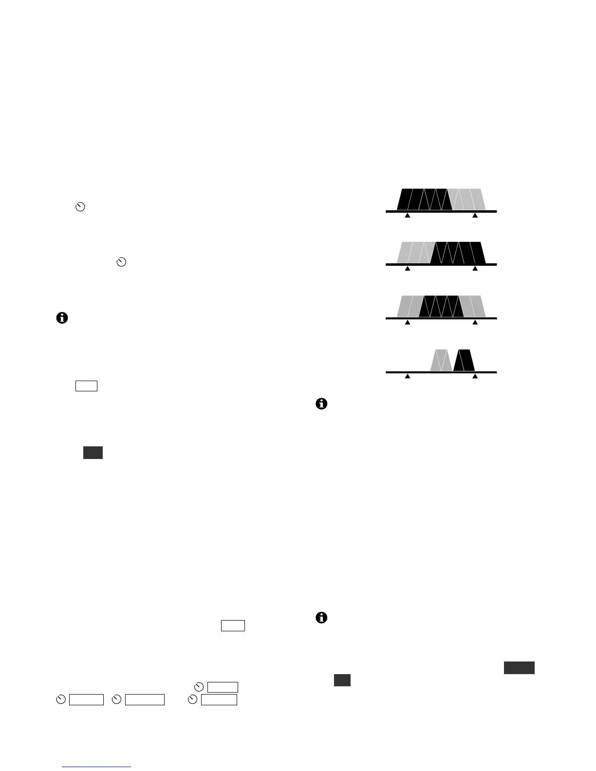
Filter Passband Controls
As you rotate the filter controls (shift, width, lo cut,
hi cut), the associated parameter value is shown on
VFO B. The filter graphic shows the width and
location of the passband, as illustrated below. In
these specific examples, segments that turned off as
a result of control movement are shown in gray.
High Cut
Low Cut
Width
Shift
Filter passband controls don’t apply in FM
mode. SHIFT control granularity can be set to
either 10 or 50 Hz in CW and DATA modes; see
CONFIG:PB CTRL. In Sync AM mode (AM- S ),
SHIFT selects the upper or lower sideband.
Each passband control has an integral switch. These
switches are used as follows:
Tapping the control alternates between the two
primary functions for that control, for example
HI CUT and WIDTH. This is indicated by the
two LEDs above each control.
Holding a control activates its secondary
function, labeled below the control.
Tapping or rotating a control shows the present
setting. To see the settings of both knob functions
without changing them, just tap the control twice.
The secondary functions of the controls are NORM
and I/II, described in the following sections.