CONFIG Menu
Save your configuration using K3 Utility after changing menu settings.
Tech Mode Entries
Menu entries that include [T] are tech mode entries. These are only visible if CONFIG:TECH MD is set to ON.
They are normally left at their defaults. Entries described as “Advanced” or “Troubleshooting” should be
changed with caution. Tap DISP to see recommended default values (in parentheses at the start of help text).
Sub Receiver Settings
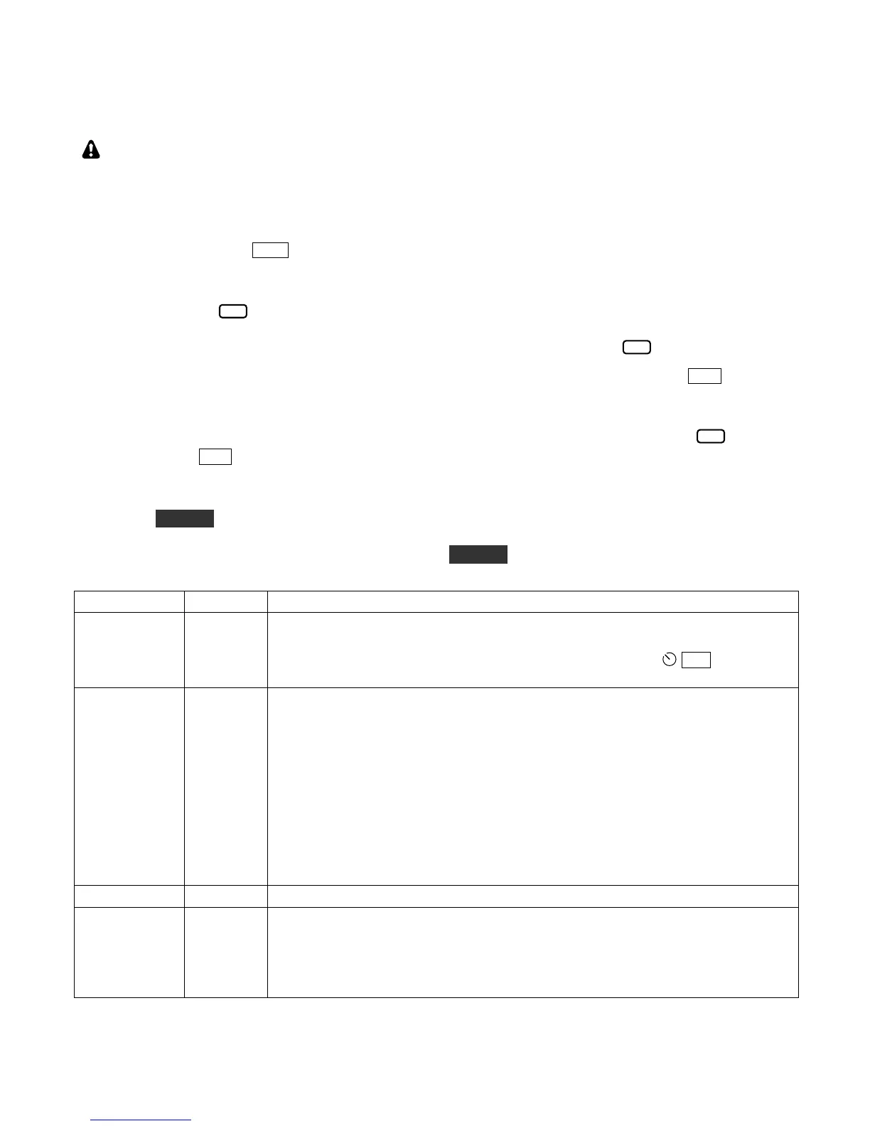
Menu entries marked have two settings: one for the main receiver, and one for the sub receiver. If a sub
receiver is installed, the menu entries will change to identify which receiver is being set up, with RF (main
receiver) or SUB (sub receiver) at the left end of the parameter. In the SUB case, the icon will flash.
Prior to adjusting sub receiver menu parameters, you should turn the sub receiver on by tapping SUB . This is
especially important if you’re adjusting crystal filter settings, because it will allow you to hear the changes as
filters are selected and modified. You should also turn SUB AF gain up and MAIN AF gain down.
Even if the sub receiver is turned on, when you first enter the menu, RF will be in effect, and the icon will
be turned off. Tap SUB to switch to the sub receiver parameter as required.
Terminal Mode (TERM)
If you hold CONFIG for 3 seconds or longer, the K3S will enter “Terminal” mode, which allows the K3S to
emulate a K3/0-Mini panel (pg. 47). In this case the K3S will not function as a radio—only as a controller for a
remotely located K3 or K3S. To exit Terminal mode, hold CONFIG for 5 seconds.
(Troubleshooting) Enables built-in 2-tone generator for SSB transmit tests. The
internal 2-tone generator only works if LSB or USB mode is selected. After
setting 2-tone ON, exit the menu and tap XMIT. You can use MIC to adjust
the amplitude of one of the tones; the other’s amplitude is fixed.
(Optional) Allows calibration of the voltage reference used by the K3S to
measure and display certain values, such as the rig’s supply voltage.
First, disconnect anything attached to the ACC jack. Next, locate the ADC REF
menu entry. It will initially show 5.00 volts as the reference voltage. Using a
DMM set to DC volts, measure the actual voltage at pin 2 of the ACC jack. This
must be done while the ADC REF parameter is being viewed in the menu.
Note: The (-) probe of the DMM should go to the chassis ground, e.g. at the
GROUND lug.
Finally, use VFO A to set the ADC REF menu parameter to what you measured
at pin 2.
Sets AF gain range. Available selections are HI or LO.
(Advanced) Adjustable AF output limiter for use when AGC is turned off. This
can protect your ears if a large signal appears. Signals or noise above the
threshold will sound highly distorted due to the limiting action, reminding you to
back down the AF or RF gain. Typical settings for those who often turn AGC off
are 17 to 23; some experimentation will be required.