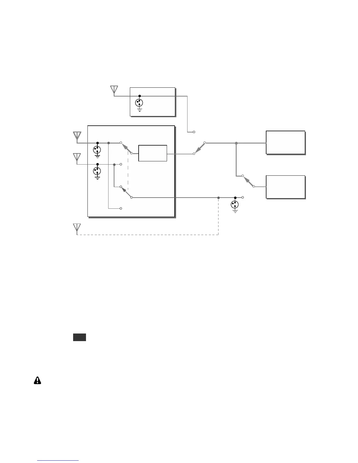
Figure 4 shows the antenna possibilities when both the KAT3A and KXV3B are taken into consideration. The
main receiver can use ANT 1, 2, or RX ANT IN. The sub receiver can either share the main receiver’s RF
source or use its AUX RF input. The sub’s AUX signal can be obtained from either the non-transmit KAT3A
antenna or the AUX RF BNC connector, as described earlier. In either case, the sub receiver’s antenna must be
isolated from the transmitting antenna.
Figure 4. Complete Main/Sub Receiver Antenna Routing
Preamp 2 Limitations
Low-noise amplifier preamp 2 is intended for weak-signal work on the 12, 10, and 6-meter bands. It can be
individually enabled on each of these bands using CONFIG:PREAMP2.
Since preamp 2 is in the main receive path, it is only available for use with the sub receiver under certain
conditions:
• The sub receiver must be sharing the main path, not using its own AUX RF source. This selection is made
by tapping ANT while in BSET mode (pg. 39). If the sub receiver is using its AUX source, preamp 2
(PRE 2) may still be used by the main receiver, while the sub receiver can have its preamp either on (PRE 1)
or off.
• The main and sub receivers must both be on bands between 12 and 6 meters.
Preamp 2 has high gain (20 dB) in order to provide a very low noise figure. If you hear signal artifacts that
suggest receiver overload, such as a rise in the noise floor when a strong nearby station transmits, switch to
preamp 1 or turn the preamp off.