Main and Sub Receiver Antenna Routing
The simplified block diagrams in this section show how antennas are routed to the main and sub receivers.
Heavy lines show the default RF path. All antennas are protected from electrostatic discharge by surge arrestors.
Receive-only antenna inputs, indicated by asterisks (*), include carrier-operated relay circuitry (C.O.R.).
Basic Antenna Routing
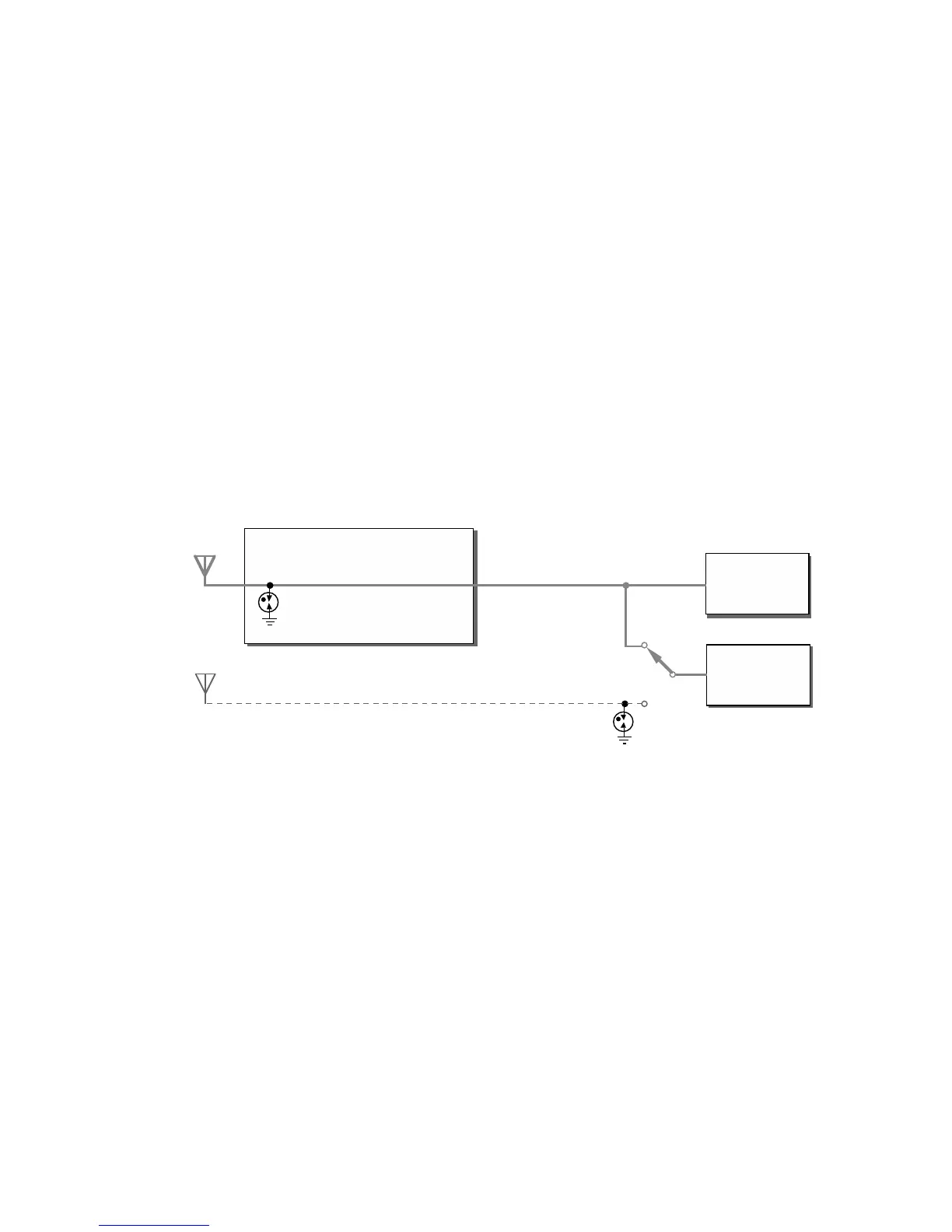
As shown in Figure 1, the basic K3S is supplied with one antenna jack (ANT1, SO-239). The signal from ANT
1 is routed through the antenna input module (KANT3) to the main receiver (as well as to the transmitter). The
KRX3A sub receiver, if installed, can share the ANT 1 signal via a passive -3 dB splitter and relay K1. When
the sub receiver is off or is switched to its AUX RF input (dotted line), K1 bypasses the splitter so it will have
no effect on either receiver.
A separate RF I/O connector for the sub receiver antenna is location is provided on the rear panel (AUX RF,
BNC). The sub receiver’s AUX RF input can be routed to this connector internally. K1 then selects either the
main RX path or AUX RF as the sub receiver’s RF source. Any receiving antenna connected to AUX RF must
be isolated from the transmit antennas so the sub receiver’s C.O.R. will not be activated during transmit. Note:
The sub receiver has its own full set of ham-band and optional general-coverage band-pass filters (KBPF3A),
but its image rejection will be best when sharing the main path, which includes receive/transmit low-pass filters.
Figure 1. Basic Main/Sub Receiver Routing (no KAT3A)
Receive Antenna (RX ANT IN)
The KXV3B module (Figure 2) adds a separate receiving antenna jack (RX ANT IN). Relay K2 selects either
ANT1 or RX ANT for the main receiver. The KXV3B is also the location of preamp 2, provided for weak-
signal work on 12, 10, and 6 meters. Some limitations apply to preamp 2 use with the sub receiver (pg. 45).
Note: The transceiver’s low-pass filters will not be in the path when RX ANT is selected. This will rarely be an
issue, since the main receiver has a full set of ham-band band-pass filters. You can use external filters in
conjunction with RX ANT IN if required.
Relay K1 allows the sub receiver to share the main receiver’s RF source, or use its AUX RF input. This means
that two receiving antennas could be used – one for each receiver.
Not shown is the RX ANT OUT jack. The RX ANT IN/OUT jacks can be used together to “patch in” an
external band-pass or low-pass filter.